Essential Guide to hsbSettings
General Tab
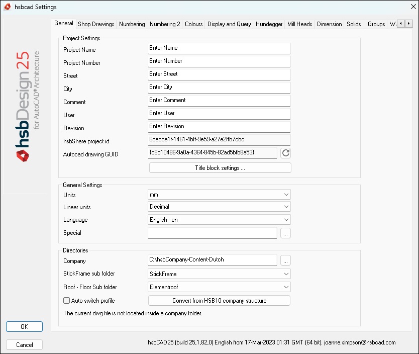
Project Settings
You can input data like
Project Name,
Project Number,
Street, City, etc.
These data are for the better identification of the project.
hsbShare project id: It's a unique id number that automatically gets generate when uploading a drawing to hsbShare, the hsbShare id matches the unique project id in hsbShare.
Autocad drawing GUID: It's a unique id number for an Autocad drawing that automatically gets generate.
BLOCK_CHECK_START
The drawing GUID, aka drawing fingerprint id, is a navite autocad property.
Whenever you make a new drawing from a drawing template, that drawing gets a unique drawing guid.
It is persisted, and will not change if you edit the drawing, save it, open it...
The drawing GUID can be used as project GUID.
In which case you want to be able to regenerate it (hence the button), in case you start your new project from an existing project.
The drawing GUID is also the basis of the entity guids.
An entity GUID is a persisted unique id.
The hsbShareId is already explained fine above.
It is used when we communicate to hsbShare from the AutoCad environment.
BLOCK__END
Title block settings - Here you can find a few predefined hsb specific Block attributes.
General Settings
You can input data like Units, linear display format and language.
The option Special is for individual settings for special companies.
Normally you don’t need this option. This is used in special cases, if hsb developers have customized the hsbcad for your company.
The value of ‘special’ is used in hsbcad to influence the standard behavior of hsbcad.
This value will direct the software to do so. Most likely this is not the case.
Only in very ‘special’ cases this is done.
The default value of ‘special’ is an empty string.
The value of the ‘special’ is not case sensitive.
The value of the special is stored in the drawing, but it is initialized from the contents of the Hsb-Special.ini file inside the Company Wall folder.
To set the contents of this Hsb-Special.ini file, press the “Save to file”-button.
Directories
You can input path’s where the software is searching for the detail drawings (e.g. for walls). This path normally gets installed automatically after installing the software.
- Auto switch profile – You can mark it to allow automatic switching between different AutoCAD profiles. The option allows you to switch between a profile of standard use of hsb and the profile to use DSP. On activation of a DSP drawing, the profile switches automatically.
- Convert from old company structure – This is used for the Version 10. The hsbcad company directories have been restructured. From this release on only one detail directory is needed. By pressing the ‘Convert’ button hsbcad will copy all relevant information from the old detail directory structure to the new detail directory.
Shop Drawings Tab
Controls the output of Shop Drawing entities.
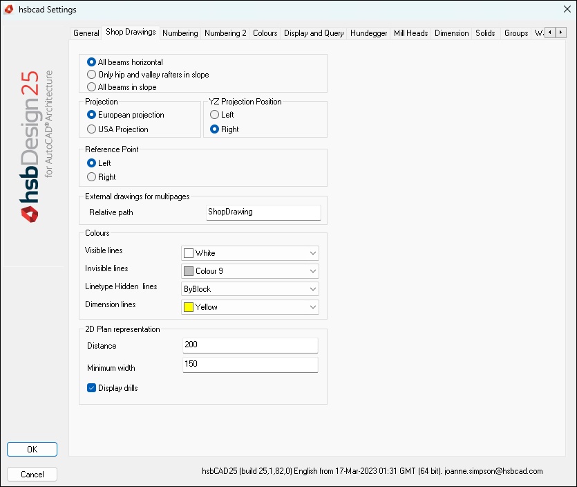
In the Shop drawings tab you can:
- All beams horizontal – Select to show all beams in horizontal alignment (also for angled beams like rafters).
- Only hip and valley rafters in slope – Select to show these beams in the 2D-drawing with the true inclination.
- All beams in slope – Select to show all beams in the 2D-drawing with the true inclination.
Projection
Select European or USA Projection.
YZ Projection position
Selecting the side view from the left or right side.
Reference Point
Select the side where the side view should be positioned.
External drawings for multipages
Colours
Select the colors of the different line types.
2D Plan representation
Select whether drillings should be shown in the shop drawing.
Numbering Tab
Controls the labeling and numbering output.
The display of the numbering is controlled in the hsbGeneral\hsbSettings dialog box on both the Numbering and Numbering 2 tabs.
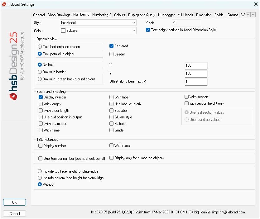
Style, Color, Text height
To specify the text height, either select a dimension style from the ‘Style’ list and controls the text height through the selected dimension style.
If using an AutoCAD dimension style to control the text, then make sure to check the setting Text Height Controlled by AutoCAD Dimension Style.
Alternatively uncheck the setting Text Height Controlled by AutoCAD Dimension Style and enter a value for the text height, usually a value between 20 and 25.
Select a color to be used for the numbering text. This is the only place to control the text color i.e. text color cannot be controlled from the selected dimension style.
Dynamic view
- Text horizontal on screen – Select whether the numbering should be positioned horizontal to the UCS.
- Text parallel to object – Select whether the numbering should be positioned parallel to the beam.
- Centered – You can define whether the number should be central on the insertion point or laterally of the insertion point. If you don’t mark Centered with a cross you can use Leader for the numbering. (also see X and Y)
- Leader – You can add a leader to the number. If you selected Centered there won’t be a leader.
- No box – select whether you want a frame/box around the numbering.
Beam and sheeting (for beams and sheetings only)
- Display number – Select whether the number should be displayed or not. This is only for the number and not for the leader and the box.
- With length – Select the properties and parameters you want to display.
- With order length – Select the properties and parameters you want to display.
- Use grid position in output – Select the properties and parameters you want to display.
- With beam code – Select the properties and parameters you want to display.
- With name – Select the properties and parameters you want to display.
- With label – Select the properties and parameters you want to display.
- Use label as prefix – Select the properties and parameters you want to display.
- Sublabel – Select the properties and parameters you want to display.
- GluLam style – Select the properties and parameters you want to display.
- Material – Select the properties and parameters you want to display.
- Grade – Select the properties and parameters you want to display.
- With section – Select the properties and parameters you want to display.
- With section height only – Select the properties and parameters you want to display.
Tsl and MetalPart (for tsl’s and Metalparts only)
- Display number – Select whether the number should be displayed or not. This is only for the number and not for the leader and the box.
- With name – Select whether the script name of the tsl should be displayed.
- One item per number – select whether similar objects should get the same number or each object should get a different number. To compare objects you have to set criteria. These criteria you can define under Parameters in the tab Numbering2.
- Display only for numbered objects – Select whether the numbering should be displayed only on numbered objects.
- Include top face height for plate/ridge – Select whether the height (bottom or top height) of the plate should be displayed or not (without).
- Without –
Numbering2 Tab
Controls the labeling and numbering output.
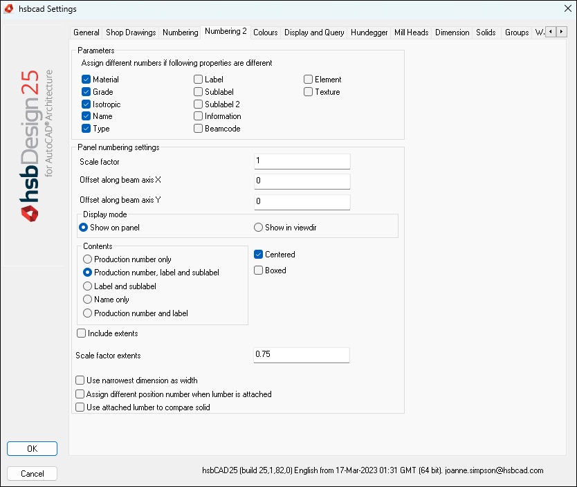
The display of the numbering is controlled in the hsbGeneral\hsbSettings dialog box on both the Numbering and Numbering 2 tabs.
Parameters
You can select the criteria to differentiate between objects. To assign different number to different objects you have to mark One item per number in the tab Numbering. E.g. if you select Material all objects with different materials are going to get different numbers.
Panel numbering setting
Scale factor – (text height) you can input a factor to make the text height bigger or smaller.
Offset along beam axis X – Offset from panel bounding box center you can input the distance between the numbering and the center of the panel in x-direction.
Offset along beam axis X – Offset from panel bounding box center you can input the distance between the numbering and the center of the panel in y-direction.
Display mode
Contents
Production number only – Select whether the information should be included in the numbering.
Production number and label – Select whether the information should be included in the numbering.
Label and sublabel – Select whether the information should be included in the numbering.Centered – Select to display the numbering centered.
Boxed – Select to display a frame/box around the numbering.
Include extents – Show panel width x length
Scale factor extents –
Use narrowest dimension as width –
Assign different number when lumber is attached (lumber install) –
Merge lumber bodies for solid comparison –
Colours Tab
In the tab Colours you can set the colours of hsb-objects.
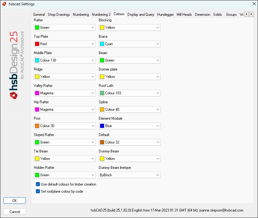
- Use default colors for timber creation – Select this if you want the timbers to automatically change color when using a different timber.
- Set roof plane color by code – Select this if you want the roof planes to automatically change color when using a different Roof code. For example Roof code A (Red), if you change this to roof code B it will automatically change color (Yellow)
Display and Query Tab
Controls the display of entities such as CNC Output.
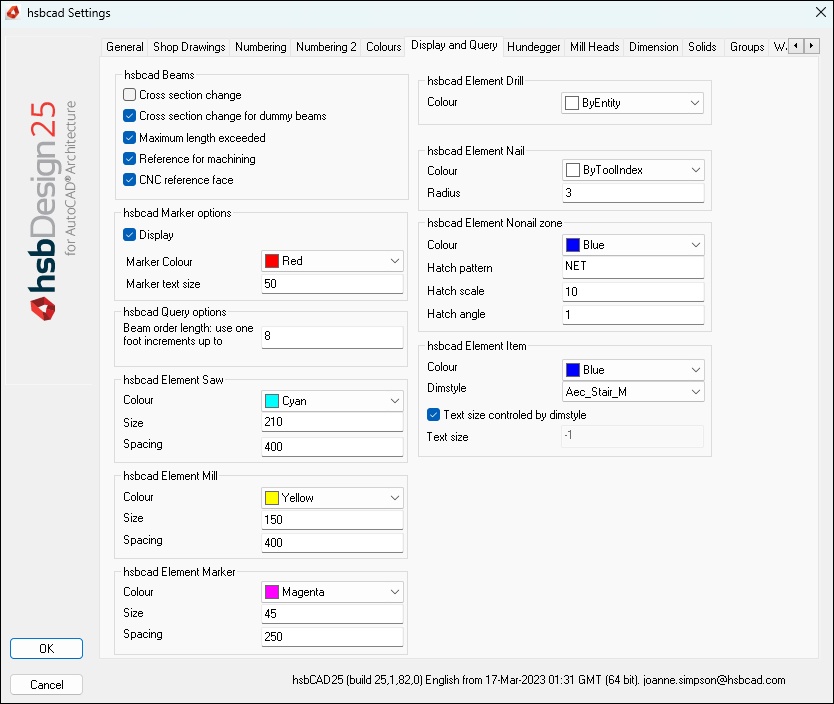
hsbcad Beams
Cross section change – Select whether you should be able to change the cross section of objects via grip points. If this option is not marked you can edit the cross section in the properties of the object and with command out of the menu hsbEdit.
Maximum length exceeded – Select whether beams should be indicated when exceeding the maximum length. You can set the maximum length in the section catalog.
Reference for machining – Select whether the reference for machining should be displayed.
CNC reference face –
Hundegger Tab
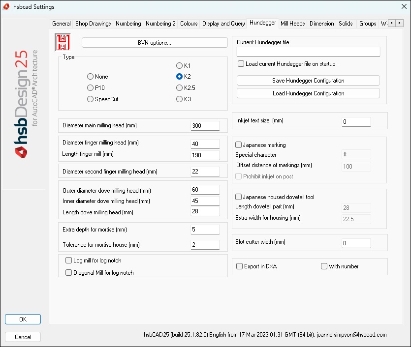
Controls output to Hundegger equipment.
In the tab Hundegger you can edit the settings for the machining and the tools of the Hundegger machine.
You can save the settings and load them another time.
Mill Heads Tab
In the tab the Hundegger 2 you can define the shape of the mill head when using a special milling tool.
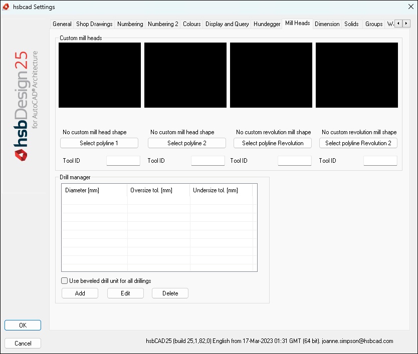
Custom mill heads
Select polyline 1 –
Select polyline 2 –
Select polyline Revolution –
Select polyline Revolution 2 –
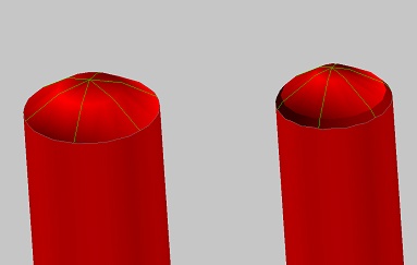
A revolution mill is a tool where a special shaped hundegger tool rotates around the beam axis to create rounded or special shaped heads. It is only accessible through tsl.
In order to use this you need
- The very latest hundegger software
- A special milling head
- A revolution mill tsl
- HH Tool ID –
Drill manager
Use beveled drill unit for all drillings –
SelectAdd –
Edit –
Delete –
Dimensions Tab
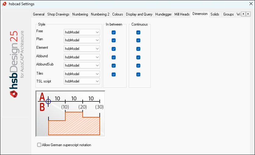
In the tab Dimension, on one hand you can set the dimension style for different fields on the other hand you can set the type of the dimension [In-between (A) / Continuous (B)].
This works in combination with hsbUtils/Dimension/Dimension Free.
Solids Tab
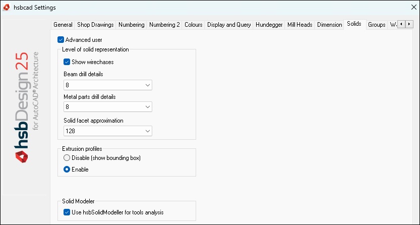
In the tab Solids you can edit the settings for the representation of solids. The better the representation of the solids the slower the software could be.
Level of solid representation
- Show panel wirechases – You can display the wire chases in panels.
- Beam drill details – you can set the accuracy of drill details.
- Metal parts drill details – you can set the accuracy of metal parts details.
- Solid facet approximation – you can set the accuracy of the solid representation.
Extrusion profiles
You can enable or disable the representation of extrusion profiles. If you disable the representation the cross section of the beams would be displayed as a rectangular bounding box.
HSB custom OSNAP settings
You can activate a special OSNAP along a beam axis or a curve.
Groups Tab
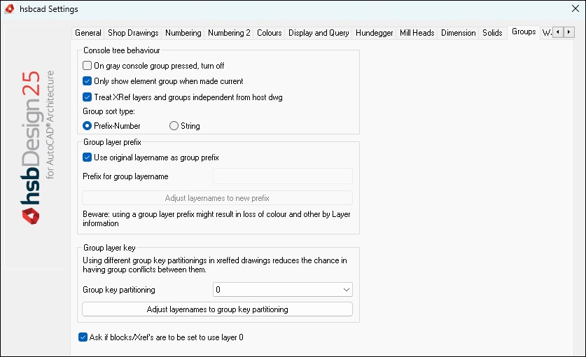
Controls the group console output and layer name prefixes.
Console tree behavior
- On gray console group pressed, turn off –
- Only show element group when made current – Select to toggle off all sibling elements.
- Toggle visibility of Xref layers too – Select to toggle off the visibility of the xrefs.
Group layer prefix
Use original layer name as group prefix – You can select whether the original layer name should be prefix for the group.
If you don’t mark it with a cross you can input your own prefix in the box (Prefix for group layer name).
Under Adjust layer names to new prefix you can add a new prefix to all existing objects.
Group layer key
- Group key partitioning –
- Adjust layer names to group key partitioning –
- Ask if blocks/Xref’s are to be set to use layer 0 –
Wall stick frame module Tab
Controls the output of the Wall stick frame module.
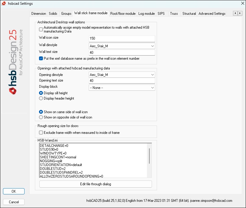
Architectural Desktop wall options
- Automatically assign empty model representation to wall with attached HSB manufacturing Data – Select if you want to switch off the ADT wall envelope.
- Wall icon size – Enter the value of the Wall icon size.
- Wall dim style – Enter the name of the Dim style.
- Wall text size – Enter the value of the text size.
NOTE: to change the arrow colour.
The arrow/text colour can be changed in the Edit object Display.
Select the arrow, right click and select Edit object Display, select the hsbcad Input displayRep and then the Edit display properties button in the right top hand corner, here you can change the colour of the Text.
How to customize the hsbWall Icon (Video)
Openings with attached hsbcad manufacturing data.
- Opening dimstyle – Enter the name of the Dimstyle.
- Opening text size – Enter the value of the text size.
Select one of the following
- Display sill height – Select if you want to view the sill height of an opening in your drawing.
- Display header height – Select if you want to view the header height of an opening in your drawing.
Select one of the following
- Show on same side of the wall icon
- Show on opposite side of wall icon
How to Customize text opening parameters (video)
Rough opening size for doors
Exclude frame width when measured to inside of frame – This is for the American market, selected it excludes the frame when ‘’Inside of frame’’ is selected.
HSB-Wand.ini
For more details see document How to set the Ini Settings
Roof/floor modules Tab
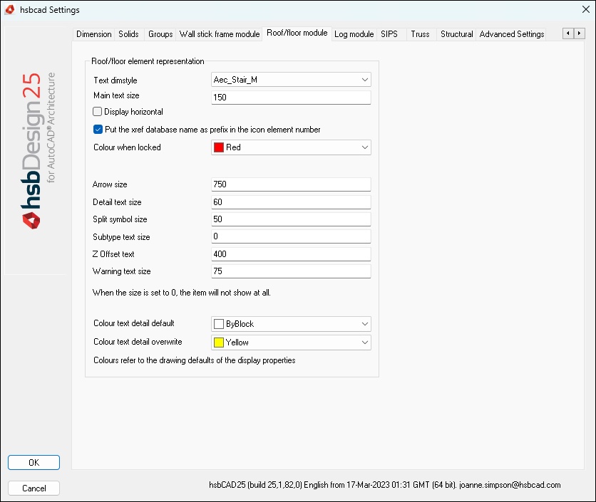
- Text dimstyle – you can select the dimstyle of the text.
- Main text size – you can input the text height.
- Color when locked – you can select a color for locked elements. (command Lock elements)
- Arrow size – input the size of the arrow.
- Detail text size – you can input the text height of the detail description.
- Split symbol size –
- Subtype text size – you can input the text height of the subtype.
- Color text detail default – you can select a color for the text of the detail description. This color is a default setting.
- Color text detail overwrite – you can select a color for the text of the detail description. This color will be used during overwriting.
Log Module Tab
Controls the output from the Log module.
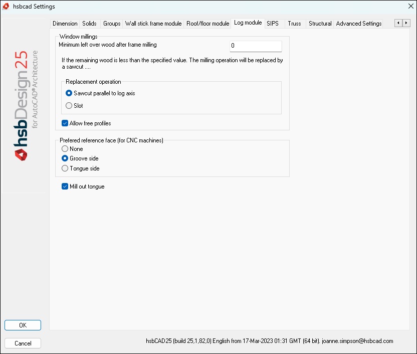
Window millings
Minimum left over wood after milling – you can input a value.
If the height of the beam minus the height of the house is smaller than the value the milling will be replaced either by a saw cut parallel to the log axis or by a slot.
This value describes the rest of the section of the beam section.
Replacement operation
You can mark Replace with saw cut parallel to the log axis with a cross to replace the milling with a saw cut parallel to the log axis.
SIPS Tab
Controls the output from the Sips module.
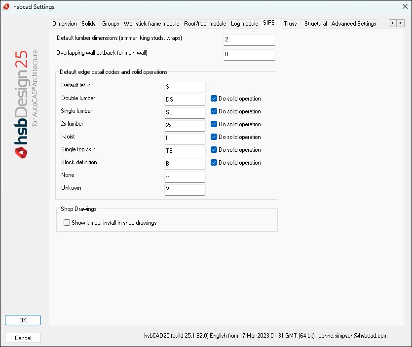
- Default lumber dimension –
- Overlapping wall cutback for main wall –
Default edge detail codes and solid operations
BLOCK_WARNING_START
Under construction
BLOCK__END
Shop drawing
Show lumber install in shop drawing –
Truss Tab
Controls the output from the truss module.
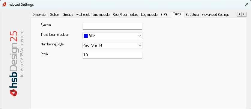
- System –
- Truss beams color –
- Numbering Style – Select a dimstyle for the numbering.
- Prefix – Enter a prefix if you want.
Structural Tab
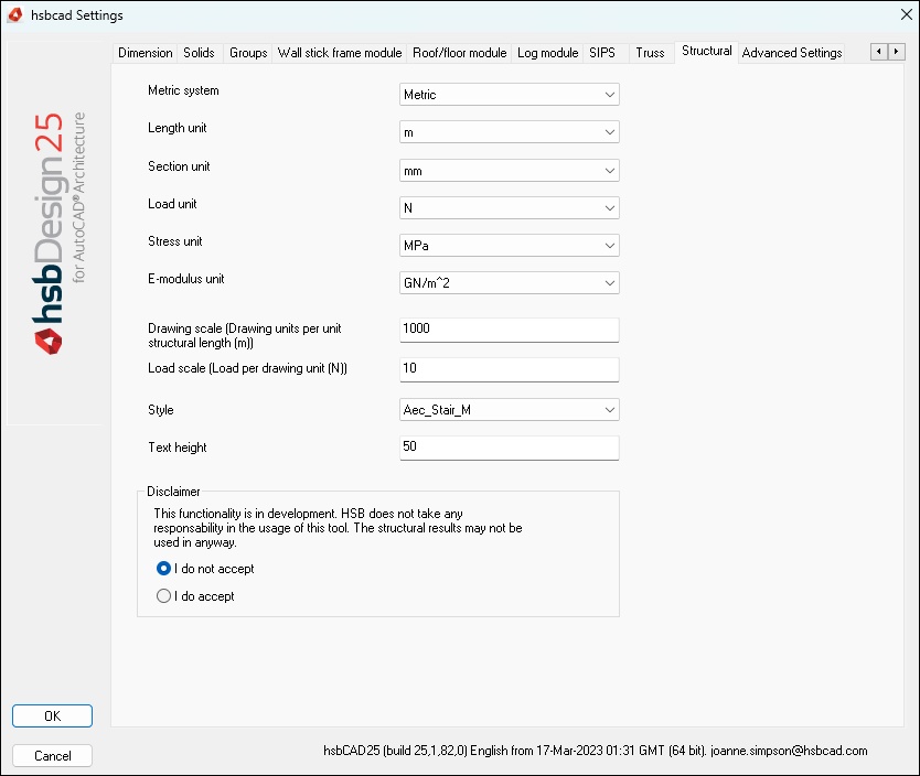
- Metric system – Select whether you want to work with the metric or the imperial system.
- Length unit – Select the length unit.
- Section unit – Select the unit for the section.
- Load unit – Select the unit for the load.
- Stress unit – Select the unit for the stress.
- E-modulus unit -Select the unit for the e-modulus.
- Drawing scale – Enter the amount of the drawing units per m.
- Load scale – Enter the load for a drawing unit.
- Style – Select the dimstyle.
- Text height – in drawing units you can input the text height in drawing units.
Disclaimer
Accept or not that the structural analysis is a new tool which is in development. And hsb is not taking any responsibility for this tool.
Advanced Settings Tab

Tolerances
You can set different tolerances. Do not change these settings without contacting hsbSoft.
Startup
- Show Tips on Startup – Switch on or off, Show Tips on Startup.
- Automatically change company folder – Select if you want to automatically switch company folder when you open a drawing, you might have drawn this in a different hsbCompany folder.
- Show registration dialog on Startup – Switch on or off, Show registration dialog on Startup.
- Show hsbcad License information – You can see what hsbcad version you have and the modules and the fingerprint information you are running on your machine.
Customization
You can import opening data’s and self-made section-, Hardware- and sheeting catalogs.
With the use of Excel you can create and edit section-, Hardware- and sheeting catalogs

