How to create an extrusion profile (Video)
BLOCK_CHECK_START
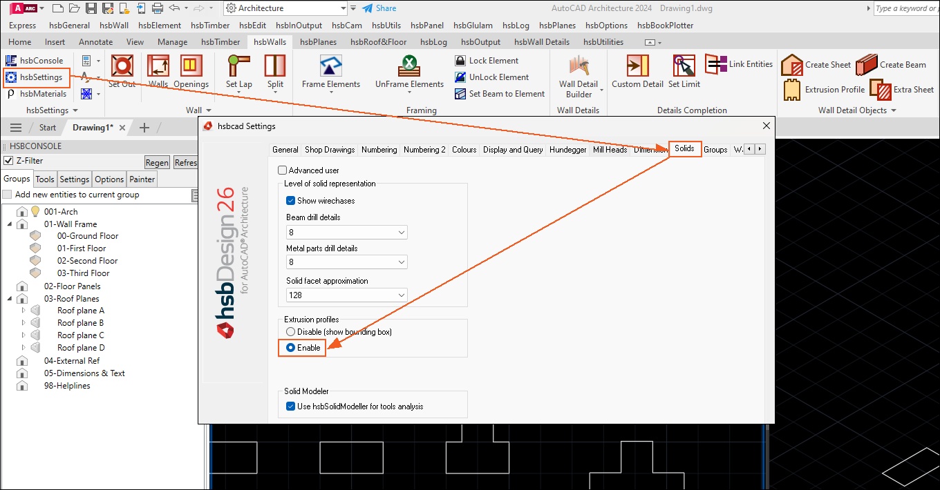
Before you start making an extrusion profile, first make sure you Enable the Extrusion profiles in the hsbcad Settings.
Otherwise your Extrusion profile will be shown as a Rectangle and not as an extrusion profile.
BLOCK__END
Available Video’s
How to make an Extrusion profile with components (Video)
How to make an Extrusion profile with a hole (Video)
How to make a Free profile in a hsbTimber or Panel (Video)
This document will show you on how to create extrusion profiles.
Step 1. Open the *.dwg profile file located in your ‘Hsb Company \Profile’ folder that has been place on your server or create a drawing and save it under ‘hsbCompany\profile’. This folder contains all the extrusion profile definitions. Any number of *.dwg files can be stored here and a *.dwg file can contain any number of extrusion profile definitions.
Step 2. Next, proceed to draw a closed polyline.
Step 3. The following graphic shows an example: the D-Log profile, it can be any profile you like but it needs to be a closed polyline.
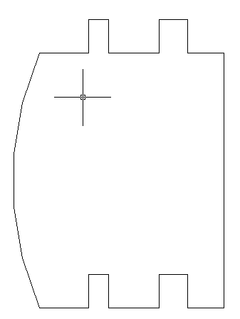
Step 4. Run the command ‘hsbGeneral\Create Extrusion Profile.’ It will prompt you to select a polyline.
Step 5. After you select the polyline the following dialog box will appear.
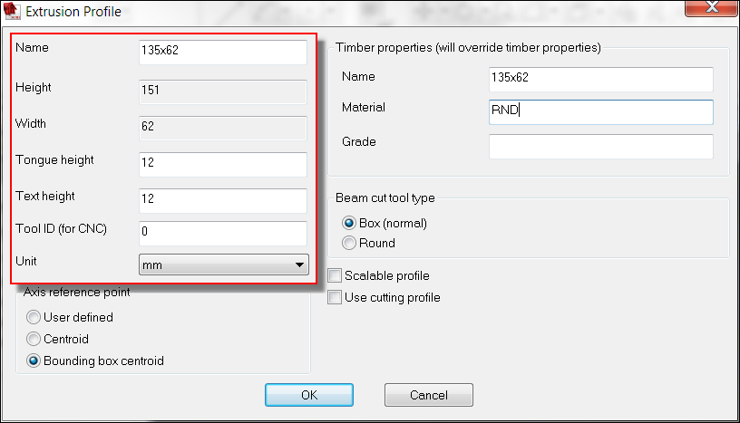
NameAllows you to enter a descriptive name for the extrusion profile E.g. ‘28x109 Plat’.HeightWill be filled in automatically.WidthWill be filled in automatically.Tongue heightEnter the height of tongue.Text heightIs the height of text of the extrusion profile object to be created.Tool ID (for CNC)Is unimportant for those who do not use CNC Machinery.UnitSelect unit from the pull down list.
Axis reference point
The axis reference point is used to specify the location of the X-axis of the profile shape.
There are 3 options available for specifying the axis.

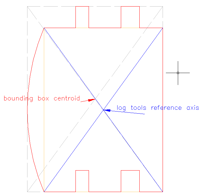
User definedUse this option to pick your own axis point along within the profile.CentroidThis option will find the center point of the profile shape based on the extremes of the profile points.Bounding box centroidThis option will form a bounding box around the profile shape and it will then find the center point of this shape and define this point as the axis of the profile.
BLOCK_INFO_START
Please note that for Log profiles, the Axis Reference Point must be set to this option.
BLOCK__END
Timber properties (Will overwrite timber properties)

NameAllows you to enter a descriptive name for the extrusion profile E.g. ‘28x109 Plat’.MaterialEnter material name.GradeEnter a grade name.
Beam cut tool type (This option specifies the tool to use for Beam cuts)
This will determine what operation is to be done when a log that uses this extrusion profile cuts another timber.

BoxYou can specify a box cut.RoundYou can specify a round cut.Scalable profileBy turning on this option, the profile shape can then be scaled automatically should you change the section size.Use cutting profileWas made especially for one particular customer, allows the user to specify holes in the profile. This is not required for log profiles.
Step 1. After the relevant information has been entered hit OK.
Step 2. The program will prompt you to: “Select reference point for log axis (ENTER to use axis reference point)”, In some cases (e.g. D-Logs) it is of advantage to have the axis of the log not running along the true bounding box centroid of the profile. The log axis will be used by the log wall tools (diagonal notch, etc.).
Step 3. Now save the drawing and close it.
BLOCK_ALERT_START
All this information will be stored in the hsbCompany\profile\*.dwg file.
BLOCK__END
How to import the profile
Step 1. The next step is to import this extrusion profile into your template or drawing.
Step 2. Open your template or drawing file.
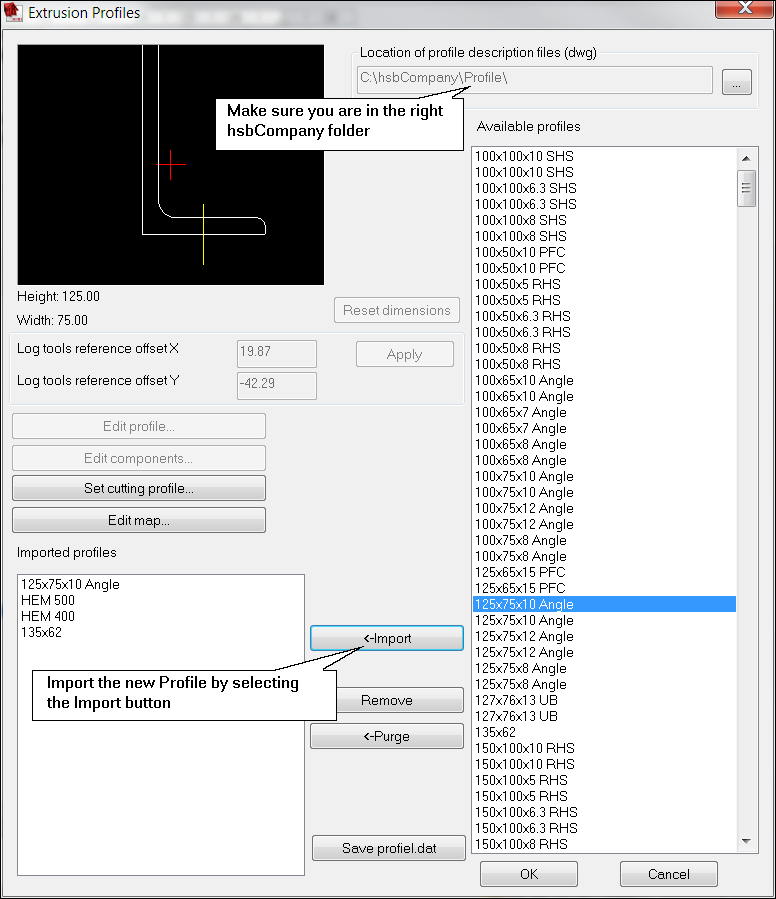
Step 3. Run the command ‘hsbGeneral\ Extrusion Profiles\ Extrusion Profile Manager’ and import the extrusion profile you have just created.
Step 4. The profile should be listed in the column titled Available profiles.
Step 5. To import the profile just select it in the list and press the Import - button.
Step 6. If the profile has been imported correctly you should see it in the column titled Imported profiles as well.
Step 7. After importing the profile press OK.
Use it as a loose hsbBeam (hsbTimber module)
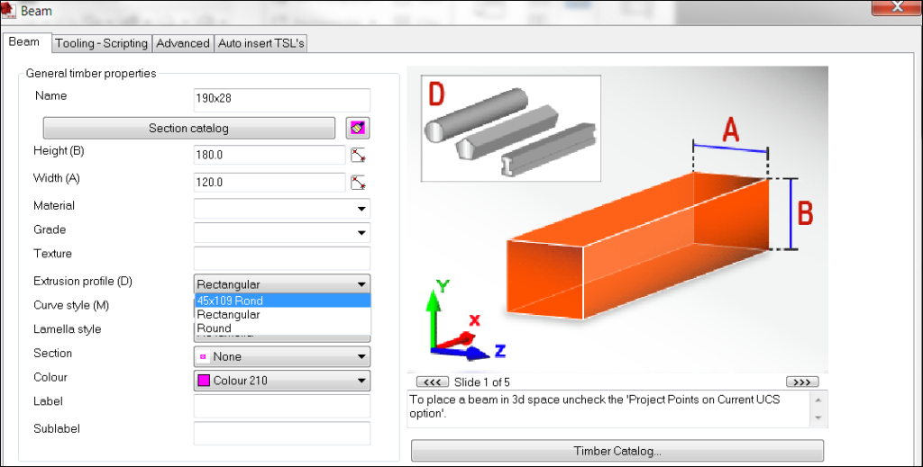
Step 1. Draw a loose beam with the command hsbTimber\Beam.
Step 2. In the Beam dialog box select the option Extrusion profile (D).
BLOCK_INFO_START
All the profiles you have imported will be listed here.
BLOCK__END
Use it in the (hsbLog Module)
When defining a log wall definition you can select an extrusion profile.
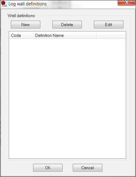
Step 1. Run the command hsbLog\ Log wall definitions.
Step 2. The Log wall definition dialog box will appear: press the New button to create a wall definition.
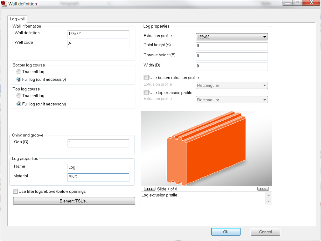
Step 3. We will now define a specific code and add more information to each log we are going to use.
Use it in the Log properties
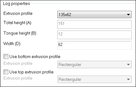
Extrusion ProfileSelect in the list a descriptive name for the extrusion profile.
BLOCK_ALERT_START
If you don’t want to see the extrusion profile in your drawing then you can switch this on\off by selecting hsbGeneral \ hsbSettings \ Solid \ Extrusion Profile\select radio button Enable (On) Disable (Off).
BLOCK__END
Total heightWill be filled in automatically.Tongue heightEnter tongue height.WidthWill be filled in automatically.Use bottom extrusion profileSelect it to use a special section shape for the bottom log course. You can select an extrusion profile under Extrusion profile.Use top extrusion profileSelect it to use a special section shape for the top log course. You can select an extrusion profile under Extrusion profile.
Now the log wall definition with a custom extrusion profile is ready to be used!
Do this for all the logs you will be using. hsblog\ Log wall definitions.
Use it in your floor or roof elements (hsbElement Module)
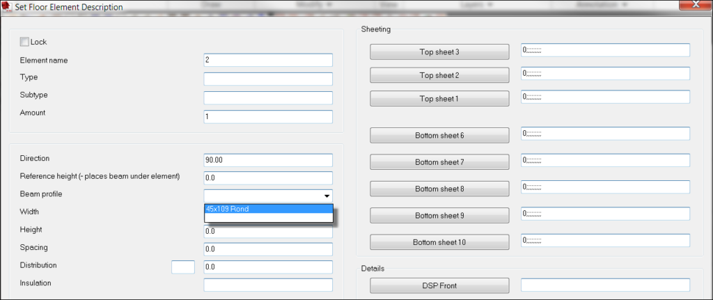
When assigning floor or roof parameters you have the option to select Beam profile.
Use it in your Wall details (hsbWall Module)
This command allows you to insert an extrusion profile in the Wall details.
Step 1. Select the Extrusion profile function in the Ribbon.
Step 2. Select an extrusion profile in the Detail extrusion profile dialog box and fill in the necessary information.
Step 3. Select with left mouse button an insertion point (center point of beam).
Step 4. Select the direction of the beam.
Step 5. Select the Link Entities to Wall outline.
Step 6. Save Detail changes.
Beam Extrusion profile (Dialog box Explanation)

NameThis is the name that you give to your Wall type.CodeEnter a certain code for the beam. This could be important if you want to use commands like saw, milling, drill, etc.MaterialEnter a material name for the beam.GradeEnter a grade name for the beam.InfoEnter additional information about the beam.Normal: Cut along cut lineThis refers to the information kept within the beam properties relating to how you will cut the beam. Normal is the default of the machine.Minimum: Perpendicularly cut as shortest position of cut lineIf there is an angle cut on the beam, the cut will begin at the closet point to the start point of the beam.Maximum: Perpendicularly cut as longest position of cut lineIf there is an angle cut on the beam, the cut will begin at the furthest point to the start point of the beam.Window codeAllows you to enter a window code e.g. code name.NailIs this beam to be nailed. Yes/no.MachineIs this beam to be machined. Yes/no.SchwelleSelect if you want a Very bottom plate.
How to make an Extrusion profile with components (Video)
This video is about making an Extrusion profile with components.
How to make an Extrusion profile with a hole (Video)
This video is about making an Extrusion profile with hole, a hollow tube
More interesting documents
Extrusion profile is not showing the actual shape
How to create an extrusion profile (Video)
How to create an extrusion profile, free profile, hollow tube (Video)
How to make a Free profile in a hsbTimber or Panel (Video)
Missing extrusion profiles in the WallDetail Builder

