How to create layouts and hsbViewport settings
Viewport Definition
The function of this document is to provide information on how to create Layouts for the use of creating manufacturing drawings and setting up viewports.
Because the automatic plotting features of hsb, update the layout for each element to be plotted, you could plot out all wall elements through just one layout, all the floor elements
through another layout etc. Therefore only a small number of layouts are required.
Layouts
A layout represents the paper setup of your drawing, containing scaled views of your model, pen settings and a printer setup.
At the bottom of the hsb screen you will see the current layouts; you can rename these and also create new ones.

Create a new layout
To create a new layout, right click on an existing tab and select New Layout.
Rename layout
To rename a layout to a more suitable name, right-click on the layout tab and select rename, enter a new name for the layout.
Layout Settings
To change the Layout Settings, make the layout current and right-click on the layout name and select Page Setup Manager. In the Page Setup Manager select modify to modify the
settings. The settings that you need to change are.
- Printer/Plotter name – Select the Printer you want to print to.
- Paper Size – Select the Paper Size to use.
- Plot Scale – Select Plot Scale(Scale of the paper) always 1 :1
Viewports
Viewports are scaled views of your model within the sheet layout. The views can have different objects visible in them.
Create a Viewport
To create a single viewport in a layout, firstly activate the Layout by left-clicking on the viewport name, and then select View\Viewports\1 Viewport. When prompted to select points, pick two points on the layout where you want the viewport to appear. You can create as many viewports as you wish within the layout.
Copy or Move a viewport
To copy or move a viewport, use the AutoCAD copy or move command.
Resize a viewport
To resize the area of a viewport, select the viewport and drag a grip of the viewport to a new position in order to make the viewport smaller or larger.
hsbcad Viewport Settings
Element Viewport Settings: Layers Tab
Element Viewport Settings: UCS tab
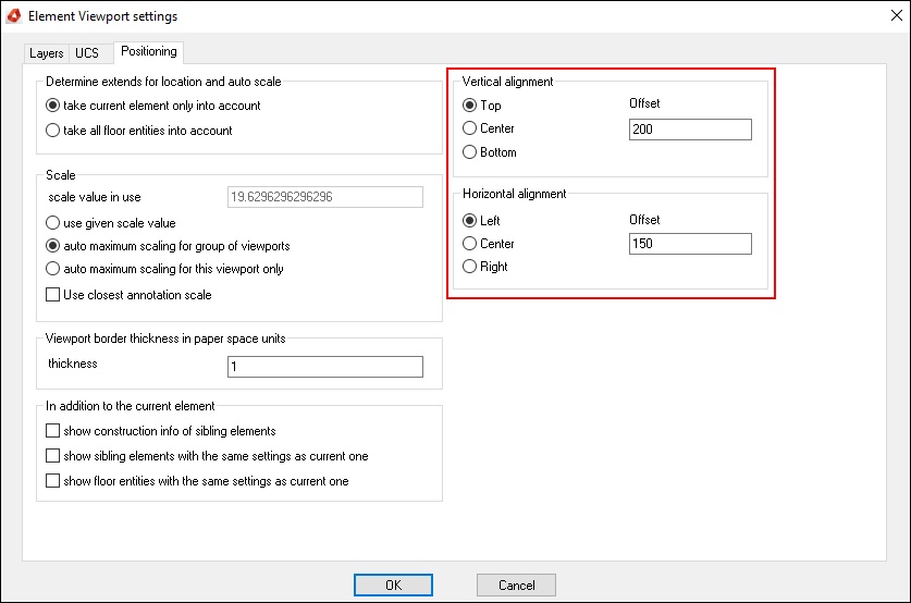
Element Viewport Settings: Positioning tab
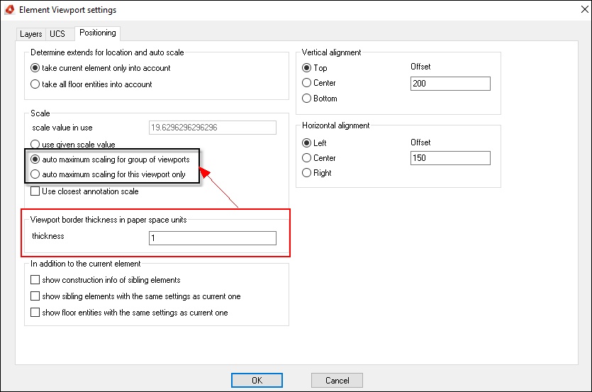
Determine extends for location and auto scale
Scale
Viewport border thickness in paper space units
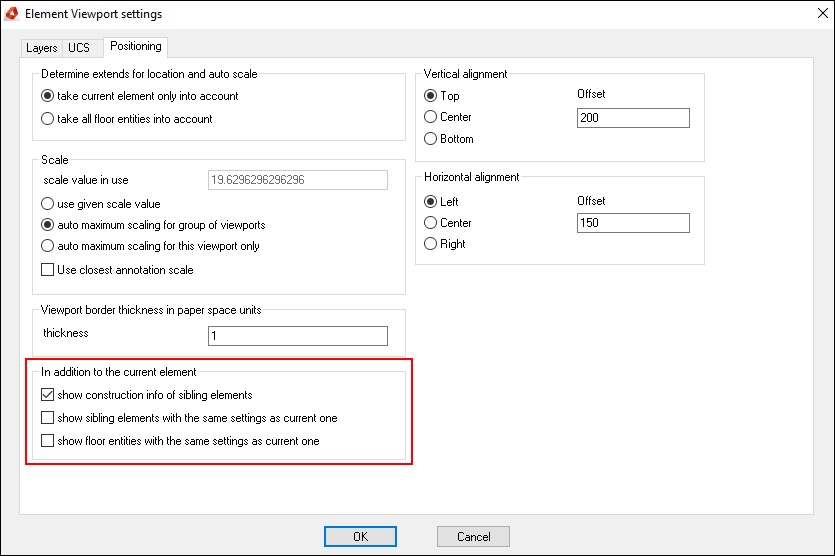
In addition to the current element
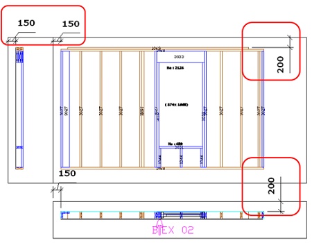
Vertical / Horizontal alignment
Even though you have created a viewport through AutoCAD, the viewport needs to be converted to an hsb viewport before you can use the hsb options to view the layout as an hsb manufacturing drawing or use the automatic plotting of hsb.
In order to view each of your viewports as an hsb manufacturing drawing, you will need to specify what layers you want to see in the viewport, the view, scale and position of your elements within the viewport.
To convert your AutoCAD viewports to hsb viewports, select hsbOutput\Viewport Settings, select the viewport and input the settings that you want in the viewport or select a viewport and right click and select hsbcad viewport settings.
Element Viewport Settings: Layers Tab
In the layers tab, select the objects associated with your elements that you want to see within the viewport. The layers tab is divided into columns and rows.
The Beam row has options to turn on the Beam (Stud, Joist etc.) and also the Construction, Tools, Number, Dimension, Info and Auto Info associated with the Beam.
Under the Beam you have Sheet Zones 1-10(Wall/Floor Sheets etc) and on each Sheet row you have the associated Construction, Tools, Number, Dimension, Info and Auto Info
associated with the Sheeting Zone.
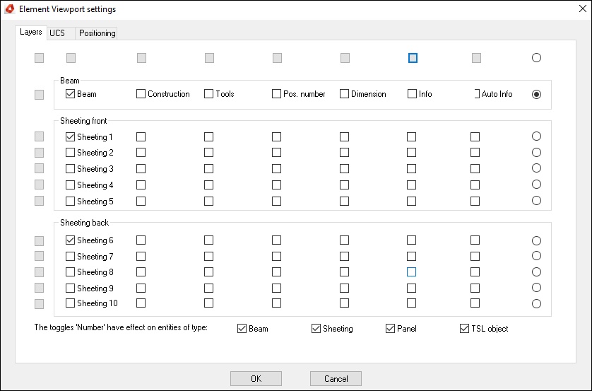
Here you define which zone is displayed in the viewport.
The first row manages the visibility of additional information as e.g. numbers of beams and sheeting.
- Beam – Show beams in this viewport.
- Construction – Shows ADT Elements.
- Tools – Shows Tools
- Pos. Number – Shows numbering of work pieces.
- Dimension – Shows Dimensions
- Info – Shows info
- Auto info – Shows Auto Info
- Sheeting front – Selected zones will be shown
- Sheeting back - Selected zones will be shown
Element Viewport Settings: UCS tab
On the UCS tab you specify what Co-Ordinate system and direction that you want to look at the element in.
The World co-ordinate system (WCS) XY, is the plane that you are looking at when you are looking down on top of your model.
The Element co-ordinate system (ECS) XY, is the plane that you are looking at when you look at the element from a point perpendicular to the element.
If you wanted to look at a side view of the element you would select Element (ECS) and set the Horizontal axis of your viewport as the Z plane and set the Vertical axis of the viewport to
be the Y plane.

X – Z: Top view (To show the backside of the wall, select Reverse)
Z – Y: Side view
X – Y: Front view
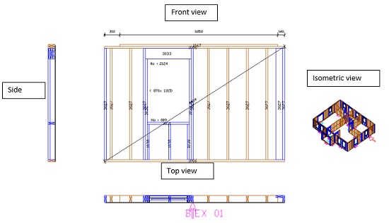
The ‘World UCS’ can be used for a display of the whole floor plane.
Element Viewport Settings: Positioning tab
On the positioning tab you set values for the scale and position of the element within the viewport.
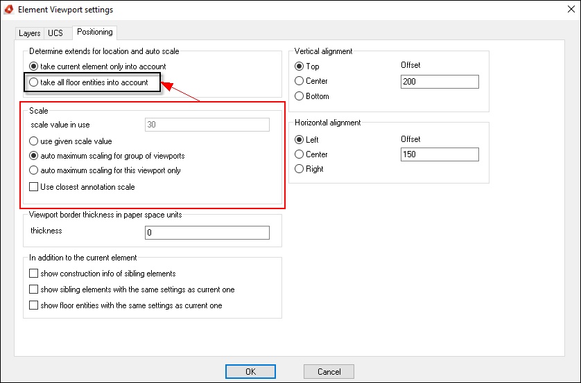
Determine extends for location and auto scale
Take current element only into account: shows the ‘Element’ you have selected.

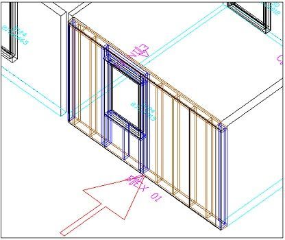
In this case we have put the USC in isometric view (NW)
Take all floor entities into account: shows all the ‘Elements’ that are on the specific floor.
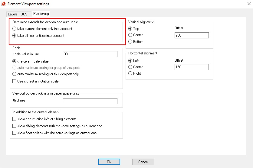
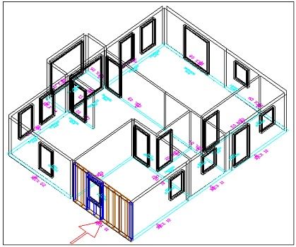
Scale
Use given scale value - When you want a fixed scaling.
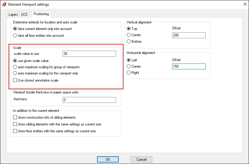
Auto maximum scaling for group of viewports - When you want automatic scaling for all elements in the same group
BLOCK_CHECK_START
NOTE: this option can’t be used if you select ‘take all floor entities into account’
All viewports have this option and will correspond with each other.
BLOCK__END
Auto maximum scaling for this viewport only - When you want automatic scaling for this viewport only
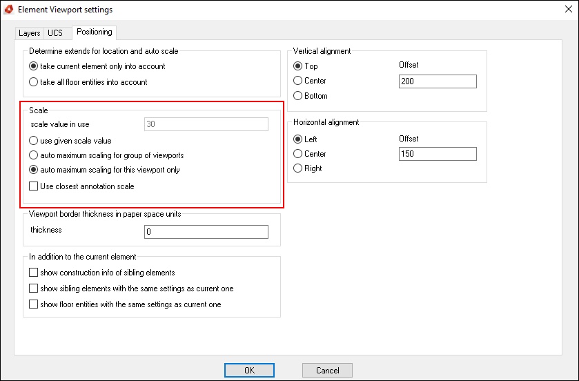
All viewports have this option and as you can see each viewport will extend to the maximum scaling of the window without taking in account each other’s viewport.
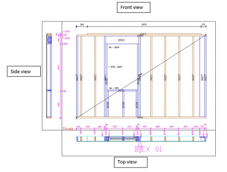
Viewport border thickness in paper space units
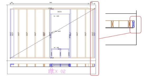
In combination with auto maximum scaling for group of viewports and auto maximum scaling for this viewport only your drawing might go to the border of the viewport (see example), when this is printed the lines will not be visible.

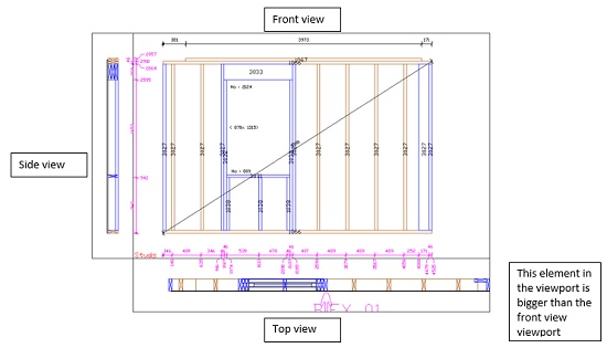
When you enter a value of minimum 1 the drawing will stop 1 paper space unit from the side of the viewport window (see example)
In addition to the current element
Show construction info of sibling elements
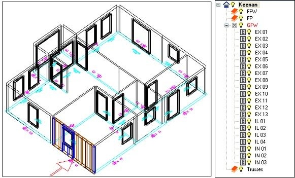
Shows panel EX01 and its siblings. (Only the model is shown)
Show sibling elements with the same settings as current one
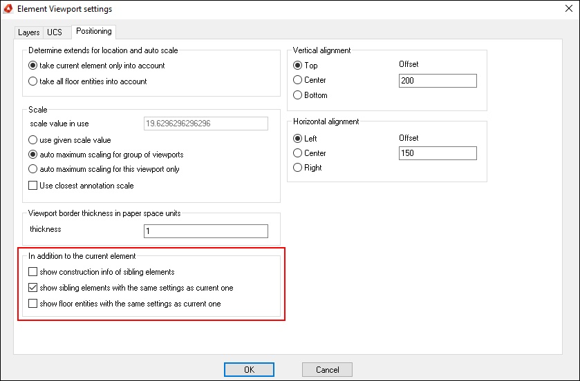
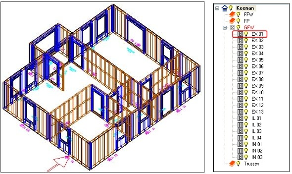
Shows panel ‘EX01’ and all other panels.
Show floor entities with the same settings as current one
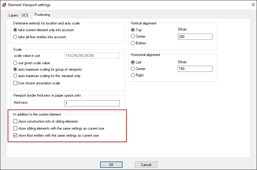
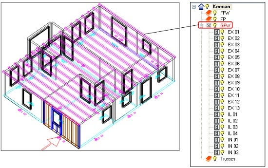
Shows panel ‘EX01’ and its siblings + all ‘Entities’ in the floor group ‘GFW’.
Vertical / Horizontal alignment
This option is used to align the drawing in the viewports.
