How to draw Planes and gable Walls
hsbWalls and Roofplanes
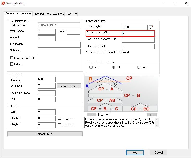
In order to create any wall that does not have a constant height, you will need to use cutting planes.
A cutting plane can be horizontal or sloped and all cutting planes will have a plane code so that you can project walls to them.
Roofplane codes
When drawing walls such as spandrels, dormer cheeks or complex shaped walls, you will give the wall a cutting plane code. Here is an explanation of different code configurations.
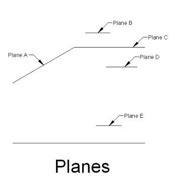
Below you will see samples of what the walls will look like if you use the sample codes in the previous page.
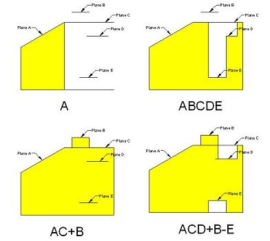
A - Goes to this plane only.
ABCDE - Goes to which ever plane(s) it meets first.
AC+B - Goes to which ever plane(s) of AC it meets first, and goes to the B plane where B is higher than A or C.
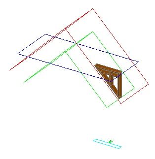
ACD+B-E - Goes to which ever plane(s) of ACD it meets first, goes to B where B is higher than A, C or D and no wall appears below the E plane.
When a minus plane is used, it must always come last in the list.
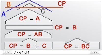
Wall is stretched to the Red (A) Plane.
Cutting Plane (CP) is ‘’A’’.
Wall is stretched to the Red (A) and Blue (B) RoofPlane.
Cutting Plane (CP) is ‘’AB’’
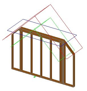
Wall is stretched to the Blue (B) and the Green (C) RoofPlane.
Cutting Plane (CP) is ‘’B+C’’
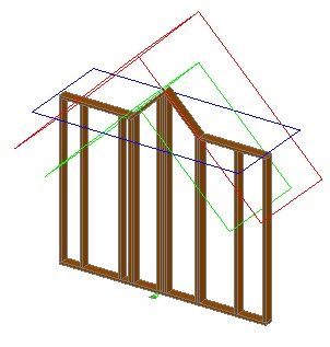
Wall is stretched to the Blue (B) and the Green (C) RoofPlane.
Cutting Plane (CP) is ‘’BC’’
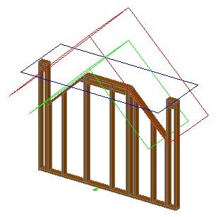
Wall is stretched to the Blue (B) and the Green (C) RoofPlane.
Cutting Plane (CP) is ‘’B-C’’
How is it Done
Set the floor height of the current group, draw the wall in the correct position and setting a code for the cutting plane of the wall.
Drawing Spandrel Walls
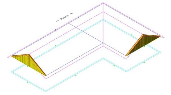
In order to create spandrels you will need to define a roof plane(s).
Each roof plane will have a plane code of one letter ranging from A-Z.
When you draw a wall you can define a cutting plane to the wall.
The wall is then projected to the plane(s).
How to do this:
- Set the floor height of the group that you want to draw you wall on.
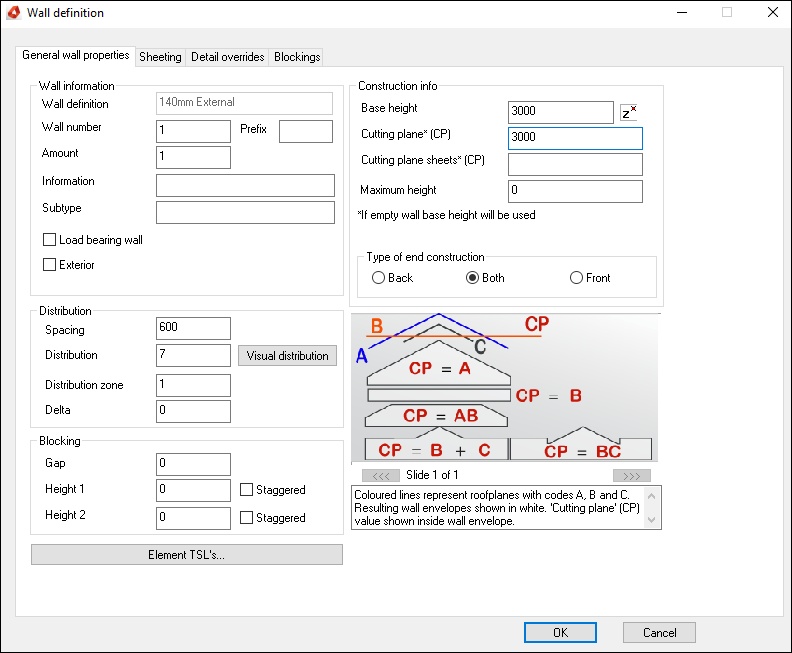
Right click the group, select Set Floor Info and set the floor height of the group to the value of the bottom of the Wall above 0. - Make the above group current and draw the wall. In the wall definition dialog box enter the plane code(s) that you want to project the wall to, make sure this plane code is entered in the Cutting Plane (CP) section.
- You may or may not have already created the plane(s). But you will have to have the plane(s) created before you can generate the wall(s).
Adjust Wall Intersection
After you have created the spandrel Walls, if the wall outline is too short/long of the roof plane, then you can use the Adjust Wall Intersection command in order to get the wall to finish
where it intersects with a roof plane. To use the command select hsbWall->Adjust Wall Intersection, select a single wall that you want to adjust, select Stretch to Roofplanes and pick
the roof plane that you want to stretch the wall to meet. You can also access the Adjust Wall Intersections command by selecting a wall and using the right mouse button.
BLOCK_CHECK_START
Note: To use this command make sure you only select one wall at a time, otherwise you will get the corner cleanup dialog instead of Adjust Wall Intersections.
BLOCK__END
Sample Exercise
- Open the drawing file spandrels.dwg which contains an outline of the outside of the timber frame and a roof plane with a code ‘A’ assigned to the roof plane.
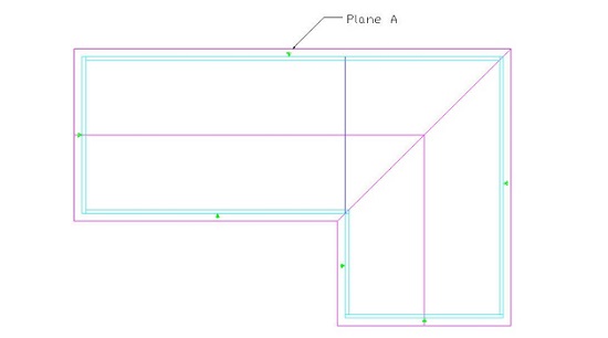
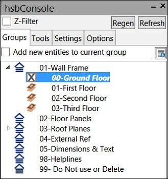
- Draw the ground Floor walls by making the group for the ground floors current in the hsbConsole.
- Select hsbWall\Place Walls, select an external wall from your wall types.
- Select to place the arrow on the right side of the wall and select right for the justification of the wall.
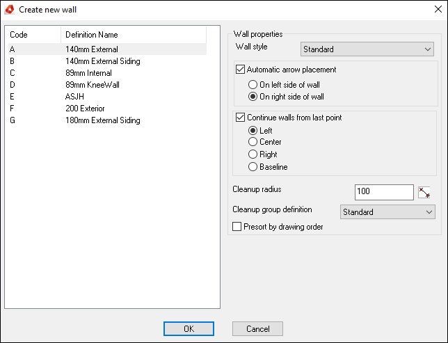
In the wall definition dialog enter the information for your ground floor wall as in the following dialog.
- Draw the walls counter clockwise for the ground floor by snapping to the endpoints of the wall outline.
To get the corners correct use the hsbWall->Adjust Wall Intersections command,
- Select 2 walls at a gable corner and pick an option from the corner cleanup dialog. Repeat this process for all the gable corners until your drawing looks like the following drawing.

Before you draw the walls make sure that they are set at the correct height.
- To do this, right click the group and set floor height to 2400, so that the Walls sit on the ground floor wall.
- Now to draw the spandrels, set the spandrel group current in the hsb console.
- Repeat the place walls command, this time on the wall definition dialog enter the information for your spandrel wall as in the following dialog.
- Make sure to enter the cutting plane ‘A’ as this is the plane that the spandrel walls are going to project to. Draw the 2 spandrel walls by snapping to the endpoints of the ground floor walls.

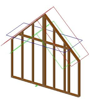
If you now shade your viewport, you should see your spandrels as in the following view.


