Metalparts
Concept
The function of this document is to provide information on how to create user defined metal parts in hsbcad.
hsbcad supports 2 concepts to create metal parts.
- A definition of a metal part can be based on a Custom entity called hsbcad Metal part collection style.
- Or it can be based on Mass Elements and Mass groups.
Metal parts based on a custom entity called hsbcad metal part collection style
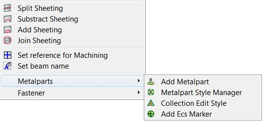
- Add Metalparts.
- Metalpart Style Manager.
- Collection Edit Style.
- Add Ecs Marker.
Metalpart style manager
An easy way of making a Collection Entity is, draw a set of hsbcad beams and run the command hsbEdit \Metalparts \Metalpart Style Manger.
If it’s the first time you use this command you need to define a style.
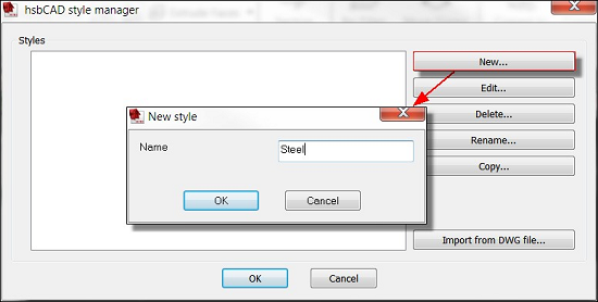
Step 1. Select the New button, the New style dialog box will appear, enter a name for the new style and select OK.
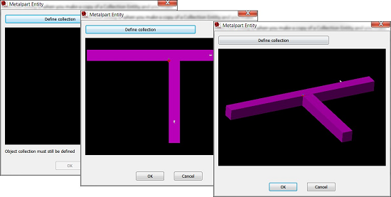
The Metalpart Entity dialog box will appear.
Step 2. Select the Define collection button.
You will be asked to select the entities in your drawing that belongs to the Collection.
The Metalpart Entity dialog box will appear again with the selected entities. (If you want to see a 3D view just select the window and with your left mouse click move your mouse around).
BLOCK_INFO_START
If you make a copy of the Collection Entity and make changes to this Collection, ALL the same Collections have changed.
If you don’t want that to happen use massgroups. (See next chapter).
BLOCK__END
To make changes to this Collection Entity style, you have 2 ways in doing this.
- hsbEdit\Metalparts\Collection Edit Style or
- Select the entity and right click and
- Select Edit Block definition, make the changes and save it.
All the Collection Entities with this style will have changed.
Metal parts based on Mass Elements and mass Groups
The user can define a metal part by drawing the representing solids. One can use any solid but in respect of automated shopdrawings it is recommended to use only those solids which can be converted into mass elements.
A collection of mass elements can be grouped to a mass group which then allows you to define mass group operations to define drills etc. For further information on how to create mass elements and mass groups see the AutoCAD Architecture Reference ‘Using Massing Tools to create Mass Groups’.
Another way of making a mass group is draw a set of hsbcad beams and run the command ‘’Massgroupadd’’ and select the beams you want to group. This will be converted to a massgroup.
BLOCK_INFO_START
The advantage or disadvantage of massgroups is when you make a copy of these and then want to make changes each massgroup is an individual entity and only the changed massgroup will be changed.
BLOCK__END

Tips using Mass elements and Mass groups
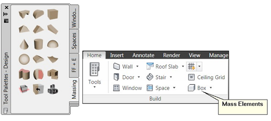
You have 2 ways in drawing Mass elements, through the Tool palette (recommended) or with the Home tab (Build, Mass elements).
Drawing a Mass element and turn it into a Mass group
Step 1. Draw a simple shape with 3 different Mass elements and add some cylindrical mass elements (drill holes) to it.
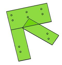
Step 2. Make the Mass elements into a Mass group by selecting the Mass group command (MassGroupAdd).
Step 3. Select only the rectangles, not the cylindrical mass elements (drill holes) yet.
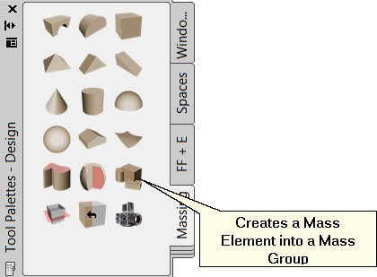
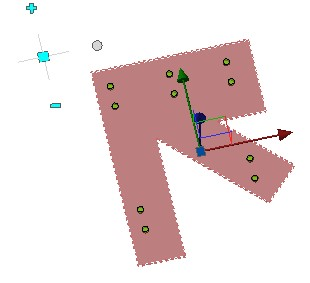
The Mass group will change color.
Now we are going to Subtract the drill holes from the Mass groups.
Step 4. Select the new Mass group and click on the + to add all subtractive Mass elements (cylindrical Mass elements (Drill holes) in this case).

Step 5. Select the elements to attach (the drill holes), you will notice that the drill holes will disappeared while the Mass group is still selected.
Step 6. select the dot (edit in place). This will turn the Mass group back into the original color (green) and the drill holes will appear again.
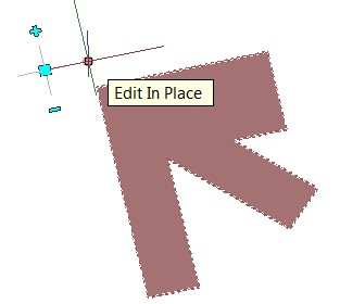
The Edit in place: Mass group tab will appear on your screen.

Step 7. Select all the cylindrical Mass elements (drill holes) and choose the operation ‘Subtractive’.
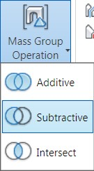
Step 8. Select Finish to close the edit in place mode of the Mass group.
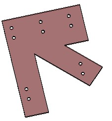
Step 9. To edit a Mass group you can use the edit in place command at any time. I.e. change the size of the cylindrical elements to modify the drill diameter.
Add this Mass group to a beam and create dynamic drill holes
Step 1. Draw a few beams in your drawing.
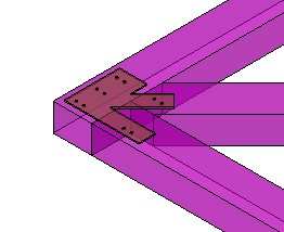
Step 2. Select the Mass group and click the Edit in Place button. You can now Edit the Mass elements separately.
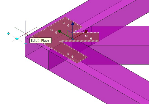
We are now going to add dynamic drills to the beams with a TSL
Step 1. Select the TSL (hsbMassElementsTool), hsbGeneral\TSL\ TSL Select, do all this while you are in the ‘’Edit in Place’’ command.
Step 2. Select the Mass elements (Drill holes) and then the beam where the holes need to be drilled in.
Step 3. Enter a depth or enter 0=complete through.
Step 4. Select enter to finish the command.
Step 5. Select Finish to complete the command.

When you move the Mass group, the Drill holes in the beam will move too.

