MultiWallComposer
How to start the MultiWallComposer
BLOCK_CHECK_START
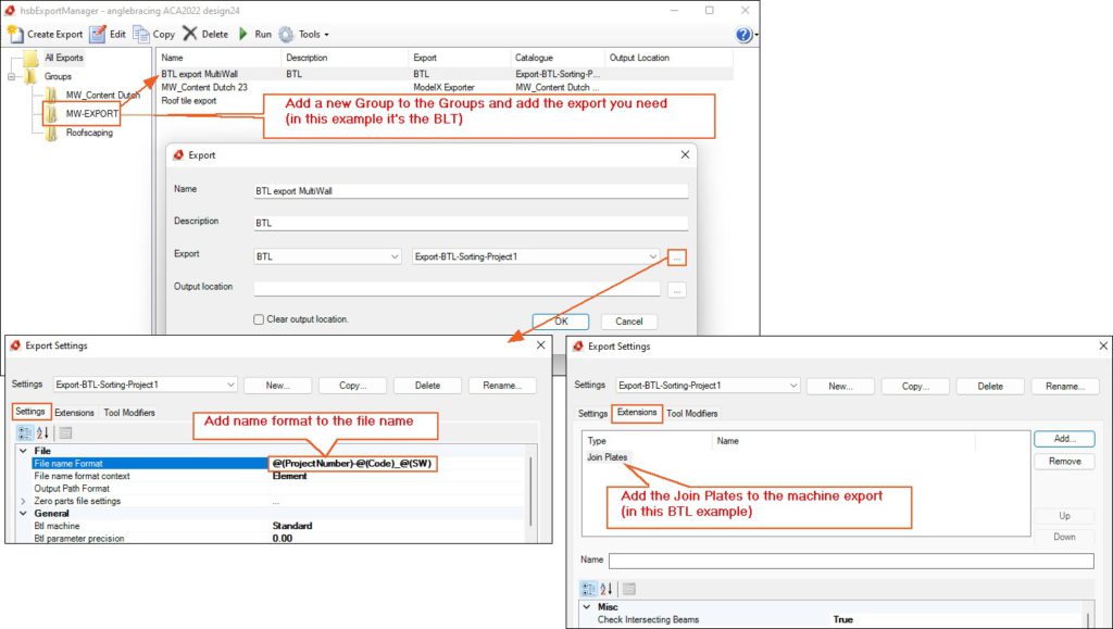
Before you start using the Create MultiWall command you need to setup a
BLOCK__END
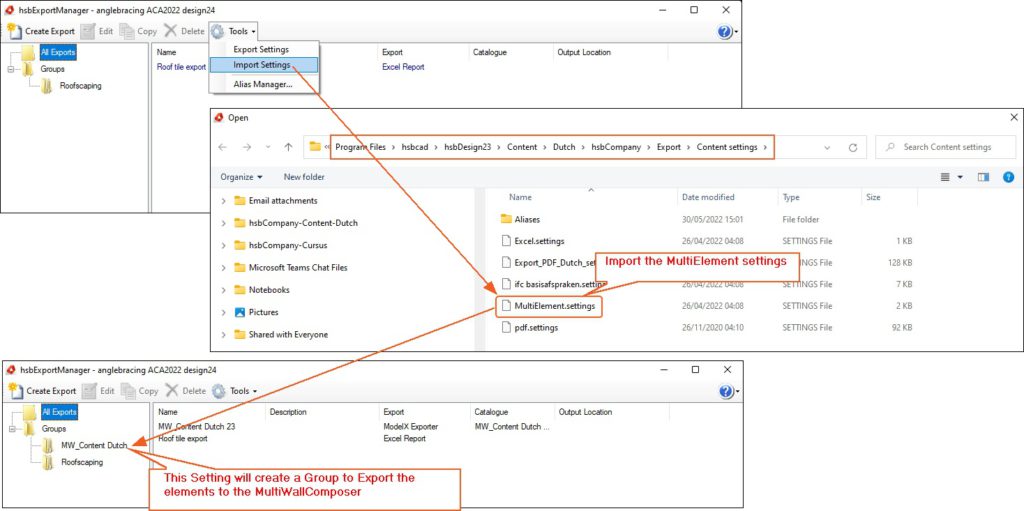
In the Exporter you need to Import the MultiElement.settings
BLOCK_CHECK_START
And you need the following tsl's in your drawing, these can be fount in the
C:\Program Files\hsbcad\hsbDesign ..\Content\General\TSL
hsb_MultiWallManager
hsb_CreateMultielements
hsb_DrawMultiElement
BLOCK__END
- Start the Multiwall Composer by selecting hsbCam\Element export\Multi element Composer OR select the Create Multiwall in the Ribbon.

BLOCK_CHECK_START
Make sure you have this drawing in a separate folder because there will be a considerable amount of files made in this folder.
BLOCK__END
This dialog box will open
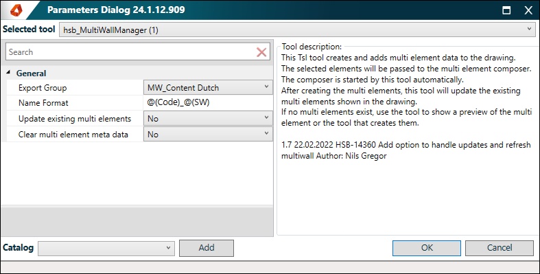
Select OK
You will be asked to Select one or More Elements in your drawing.
The Output Folder dialog box will open (See below).
BLOCK_ALERT_START
Before you start importing Elements to the Multiwall Viewer set some options in the MultiWall Options first.
BLOCK__END
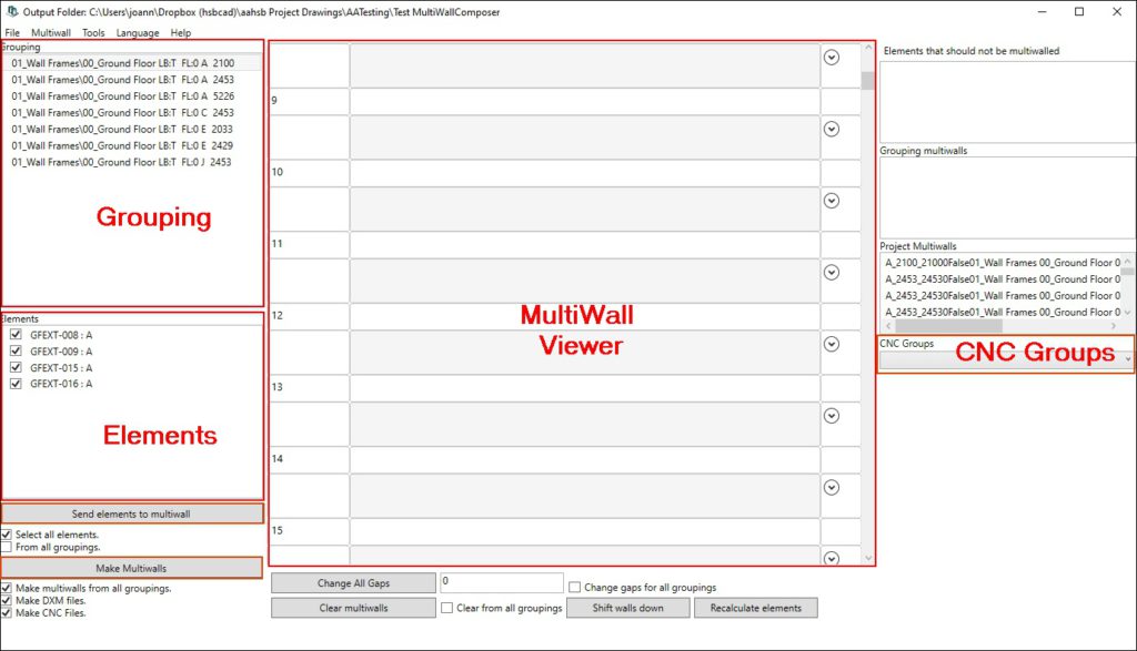
Grouping – Here you will find the elements arranged by Wall type and width, Width of the table, in hsbcad this would be the Base height. These settings can be changed with different
options (Multiwall\Options). Default are the settings you see in theis example
Elements - Here you will find the elements in numerical order per group of Wall type.
Multi Wall Viewer – Right hand side of this dialog box, you have a selection of 15 Multiwall viewers.
Send Elements to Multiwall – When selected you send the elements to the MultiWall Viewer.
Make Multiwall – When selected you create MultiWalls, this will be export to a file depending on what options you have selected. (Options under the ‘’Make Multiwalls’’ button).
CNC Groups – Select the cnc Export in the pull down you desire (BTL-WUP-bvn), one of these files needs to be made first in the cnc Exporter (hsbCAM\Element export\Cnc Exporter).
How does the Multi Wall work
You have 2 ways of moving the Elements to the Viewer Window
1. By dragging
2. Automatically
Each Viewer window represents a MultiWall table were you make a MultiWall.
In this case we have made the table length 12000 mm (See Setting Options).
To make a Multiwall you need to place each Element in one of these windows.
1. By dragging
By default all the elements will be Checked, you can only drag Elements that are checked, drag an element to the MultiWall Viewer with your mouse.
You will notice that a tab will be created with each Element you drag to a Viewer window, this tab has the Element name.
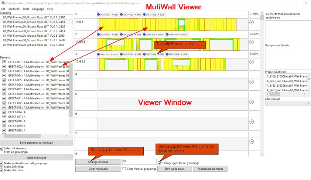
2. Automatically
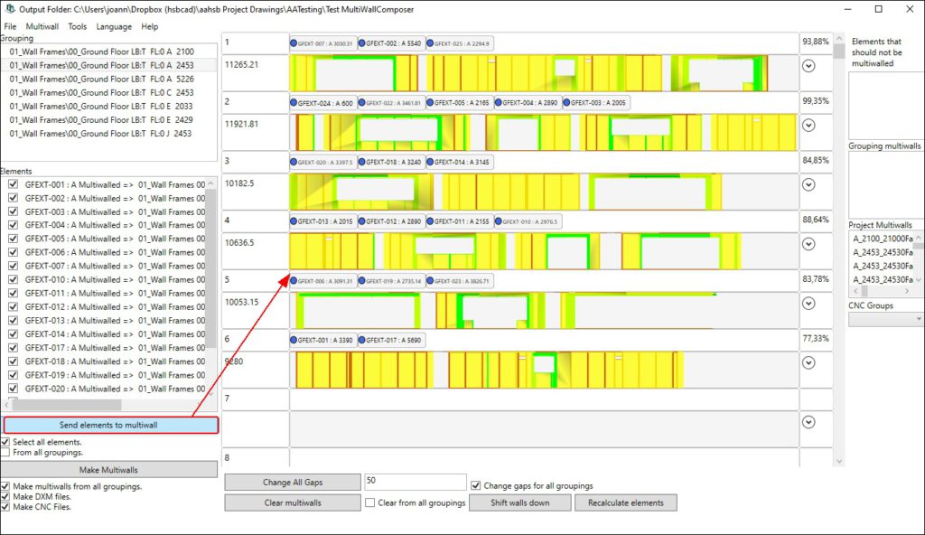
By default all the elements will be checked, if you don’t want all Elements to be selected you can deselect the ones you don’t want to process, now you can select the Send Elements to Multiwall button.
The Elements will automatically be send to the Top Viewer window.
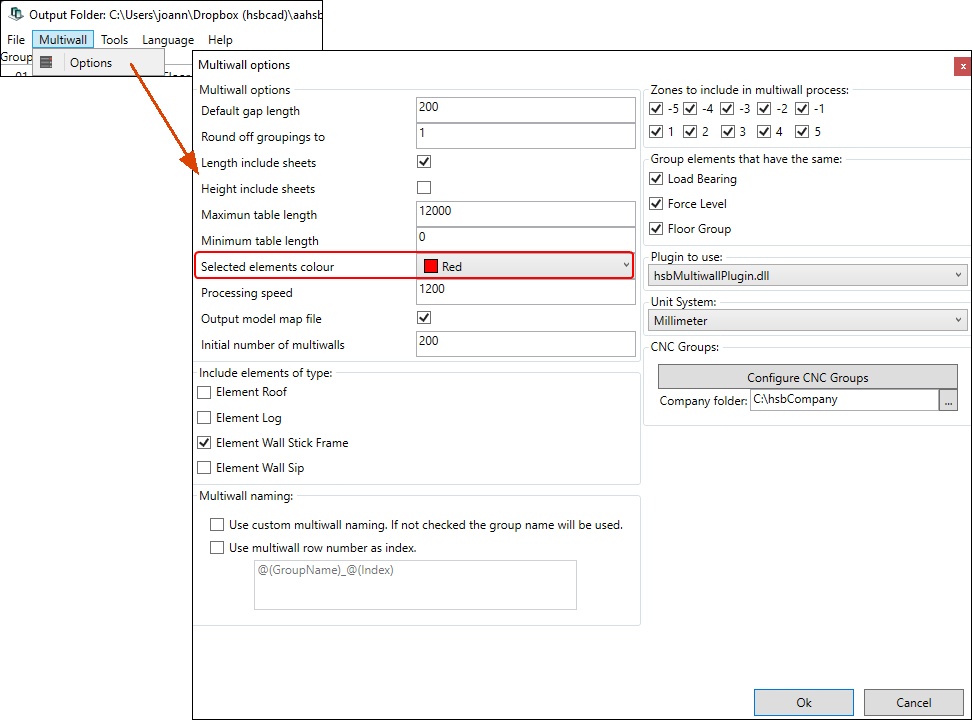
- Select the Element Tab and the Element in the MultiWall viewer will change color. (Colors can be changed in the option (Multiwall\Options).
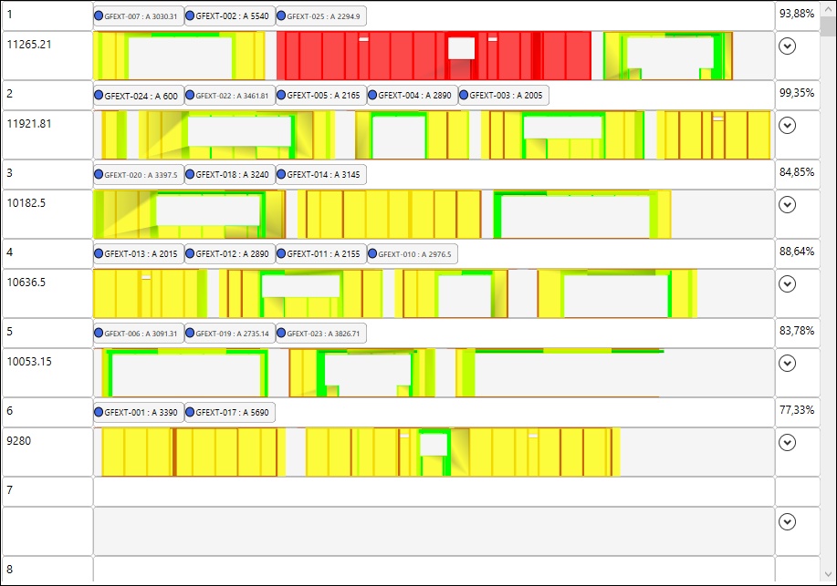
When you want to drag an Element to another MultiWall Viewer Window you select the tab and drag it to the Viewer window.
VIEWER WINDOWS
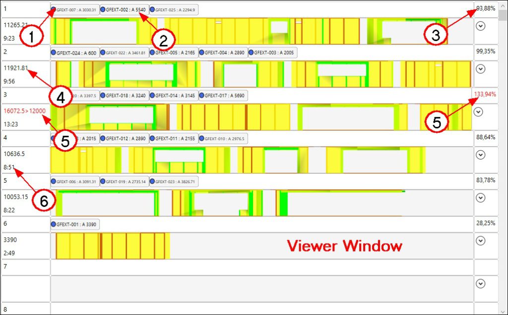
When you have dragged a few Elements to each MultiWall Viewer window you can see the Element name, Element Length, the total length of the Multi Wall table
(and if it exceeds the table Length, it will appear in red)
1 - Element Name
2 - Length of each element
3 - Percentage of MultiWall table coverage
4 - Total length of the Multiwall
5 - When the Total length exceeds the table length it will turn RED
6 - Time that will take to make this Multiwall (units/min)
DETAIL VIEWER
When you double click a Viewer Window a 3D view (Detail viewer) will appear on the bottom side of the dialog box.
Here you have the option to visually see the size of the table (Elements Visible).
- Switch on/off the Elements Tools, sheets, beams and Sips.
- Double click the Detail Viewer to leave the application.
You have the use of the AutoCAD views.
You have the use of visual styles (Solid, Edge, Outline).
You can move (Orbit) the drawing by selecting the Element in the Detail viewer and move (Orbit) your mouse around.
1 - Double click the Viewer Window to get a 3D view of the Table
2 - Select to get an Isometric view
3 - Double click the Detail Viewer to leave the application

Make Multiwalls
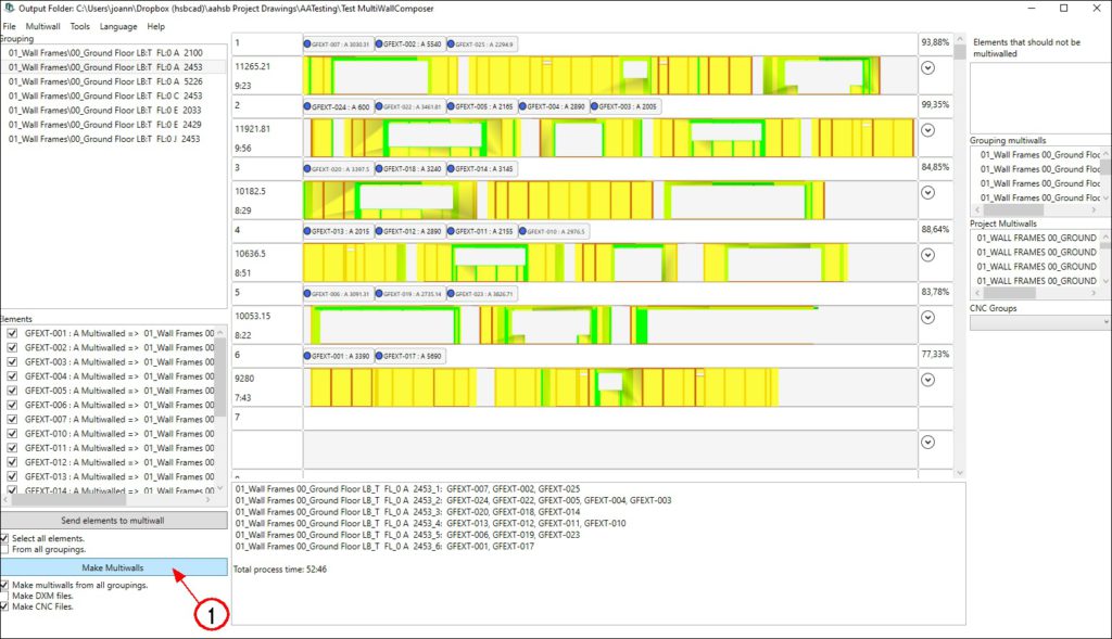
Once you have moved all Elements to the Multiwall viewers you can start making the Multiwalls.
- Select the (1) Make Multiwalls button, don’t forget to select the options below this button.
You can Make Multiwalls from all groupings (This needs to be selected if you want to export to a *.dmm file)
You can export to a *.dxm file (hsbcad file)
You can export to a cnc file. (wup\bvn\btl…)

BLOCK_CHECK_START
The files will be stored in the folder where your drawing is saved.
BLOCK__END
MultiWall Options
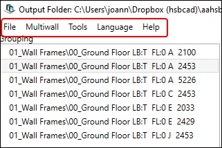
Multiwall Tab – Options
BLOCK_WARNING_START
Before you start importing Elements to the Multiwall Viewer set some options in the MultiWall Options first.
BLOCK__END

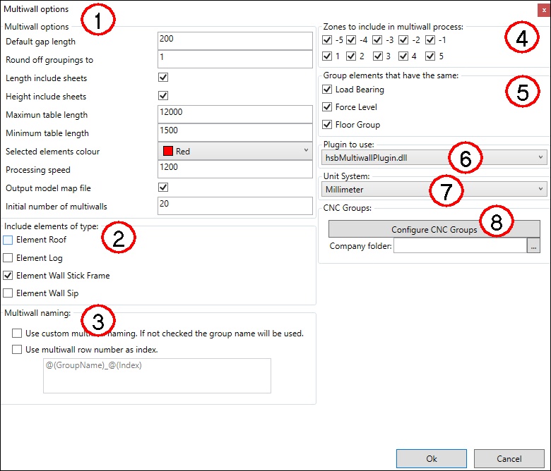
1. Multiwall Options
Default gap length – Enter the Gap between 2 elements.
Round off groupings to - Enter a value for rounding off the groupings (This means you can round off the width of the table, eg you have an Element that is 2453mm wide, you can round this off by 5 and it will change to 2455mm). IMPOTANT: you have to open the project again for the changes to work.
Length includes sheets – Check or uncheck the box. If the length of the elements includes sheets it’s ‘’checked’’, f it does not include sheets it’s ‘’unchecked’’.
Height includes sheets - Check or uncheck the box. If the height of the elements includes the sheets it’s ‘’checked, if it does not include sheets it’s ‘’unchecked’’.
Maximum table length – Enter the max length of the Multi Wall table.
Minimum table length – Enter the min length of the Multi Wall table.
Select element colour – Select a color you want the element to be when you select it.
Processing speed – Enter the seconds and the units are in m\sec, if you don’t enter a value the time will not be displayed.
Output model map file - Check or uncheck the box. If checked the MultiWall Composer will output a *.dmm file in the output folder, the checkbox Make Multiwalls from all groupings needs to be checked.
Initial number of multiwalls – Default you will get 200 Viewer Windows, in hsbcad 2013 (V18) this can be changed to less.
2. Include elements of type

- Select the element types you are using.
3. Multiwall Naming

4. Zones to include in multiwall process

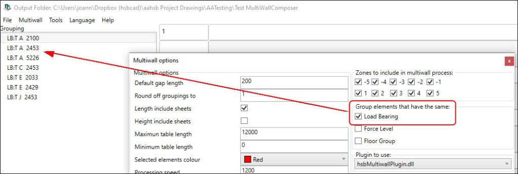
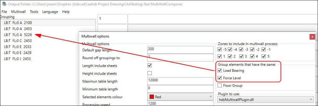
5. Groups elements that have the same
Select what you want to see in the Grouping list


6. Plugin to use

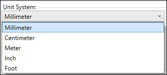
7. Unit System
- Select in what units you want to work in.
8. CNC Groups

Tools Tab
BLOCK_WARNING_START
From hsbDesign 23 onwards a Fingerprint License is not needed this will run with your online myhsbcad Account.
BLOCK__END

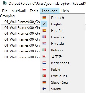
Language Tab
Select the language you want the MultiWall Composer to be in.
2. Standalone installation
The hsbSetup is pretty straight forward.
Once you have an Myhsbcad Account you can go to the our Download Center in https://myhsbcad.com/downloads
- Select the hsbDesign Components

