How to make hsbWall details in hsbcad 2017 (Video)
This document will show you how to make hsbWall details in the older version of hsbcad 2017
How to Define a New hsbWall
Before you start working with the hsbWall Details make sure your hsbCompany is set to the right Stickframe.
To define a New wall run the command hsbWall\hsbWallDetails\Open Wall Detail Interface or select hsbWall Details in the Ribbon

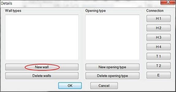
- Select the option New wall in the Details dialog box.
You will than get the following drawing that will open in hsbcad. As you can see it’s an empty drawing without any details in it yet.
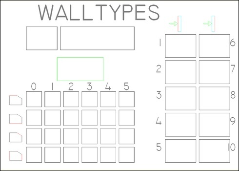
- Select hsbWall\hsbWallDetails\Create Wall type or select Create Wall in the Ribbon.

- Fill in the Wall type dialog box and select OK. (More explanation can be found in Chapter Create Wall type (Dialog box Explanation)
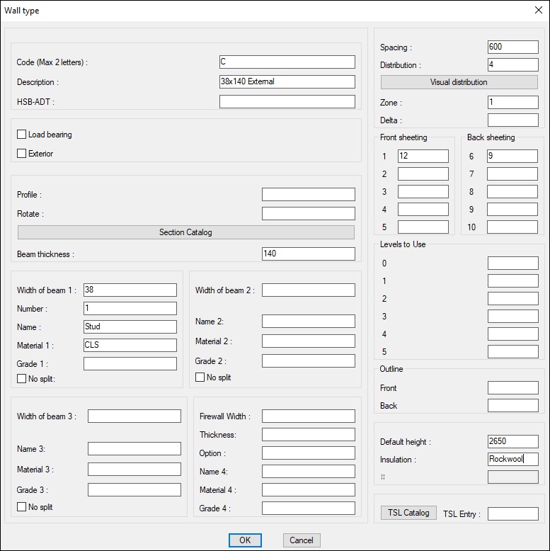
After you have filled in the Wall type dialog box, run the command hsbWall\hsbWall Details\Upload New Details.

- You will see the wall details appear in the squares in your drawing that has opened.

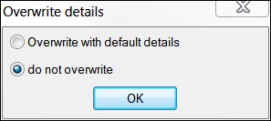
- Select overwrite with default details and confirm with OK.
BLOCK_INFO_START
NOTE: for example if you change the name of a wall but the sections of the studs don’t change, you should select do not overwrite detail. In this case you don’t overwrite the existing details. The option Overwrite with default details you should select if you define a new wall or you want to change the section of the studs.)
BLOCK__END
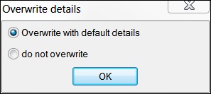
If you have entered a value in the sheeting zones (e.g. zone 1 and 6) you will get the following messages.
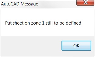
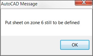
- Select OK in both cases.
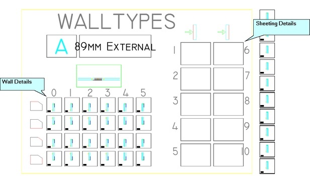
The Wall details will be automatically filled in.
How to Define a sheeting (Create Sheet)
Now you need to define the 2 sheeting zones you have created (in zone 1 and zone 6).
- Select the Create Sheet icon in the Ribbon.

- Select the first window nr1 of the sheeting zones of the detail drawing.
- Fill in the Wall Zone dialog box and select OK.
Sheeting Types
More on what sheeting types to choose from can be found in Sheeting Types documentation.
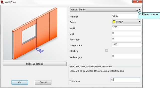
- Repeat this for Sheeting zone 6. The sheeting zones are now defined.
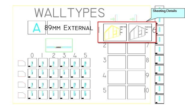
- Select hsbWall\hsbWallDetails\Save Details Changes or Save Detail in the ribbon, your first Wall Types has now been defined.

How to Create an Opening Type
With the command Open Wall Detail Interface you can call the Details dialog box.
To define a New opening type run the command hsbWall\hsbWallDetails\Open Wall Detail Interface or select hsbWall Detail in the Ribbon.

- Select the option New opening type in the Details dialog box.
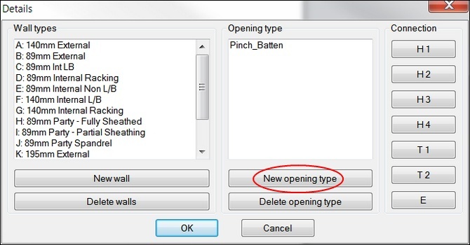
- As you can see it’s an empty drawing without any details in it yet.
- Select Update new details and give the opening detail a Name in the command line of Autocad.
- All the predefined walls will appear in the drawing.
BLOCK_INFO_START
NOTE: You have 3 rows per wall type, top row is the top detail of an opening, Middle row is the bottom detail of an opening, Bottom row are the Side details of en opening.
BLOCK__END
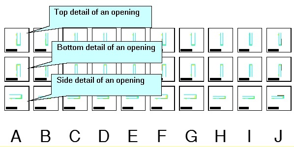
- Do the changes and save the drawing with the command Save Detail.

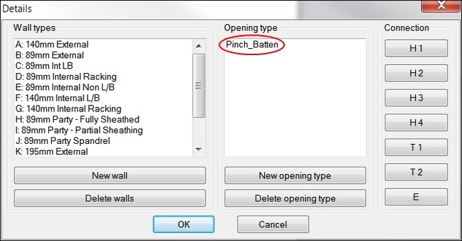
- Your New Opening type has to been created, you can now see it in the Detail dialog box.
- If you want you can edit it any time just by selecting the name of the opening detail.
When using limits in opening Details you must give the surrounding beams a Window positioning code.
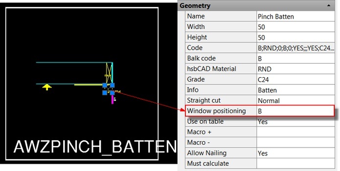
Name – Enter a name for the beam.
Width– Enter the width of the beam.
Height – Enter the height of the beam.
Code – Do not enter anything, this info is a combination of the Balk code/hsbcad Material …. ect.
Balk Code– When using limits, enter a Beam code.
hsbcad Material– Enter the beam material.
Grade – Enter the grade of the beam (strength of the beam).
Info – Enter extra information.
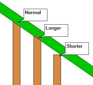
Straight cut – Select Normal/shorter/Longer. Will take the longer or shortest beam length.
Window positioning – When using limits in opening Details you must give the surrounding beams a Window positioning code.
Use on table – Select Yes or No. (Does this need to be exported to the Weinmann machine).
Macro+ – This is obsolete (used by older hsbcad versions)
Macro- – This is obsolete (used by older hsbcad versions)
Allow Nailing – Select Yes or No. (Do you allow the nailing on this beam)
Must calculate– ………………
How to Edit an Opening Type
Before Editing an opening you have to have created one (See How to Create an Opening Type above).
- Select hsbWall \ hsbWallDetails \ Open Wall Detail Interface.
- The Details dialog box will appears.

- Select an existing Opening type.
- The Opening type drawing will open.
- Do your changes and save the drawing with the command Save Detail.

How to Edit an existing hsbWall Details
With the command Open Wall Detail Interface you can call the Details dialog box.
With the help of this dialog box you have access to Edit/Delete existing Walls, Edit/Delete Corner connection and to all the different wall and Edit/Delete Opening types.

Details (Dialog box Explanation)
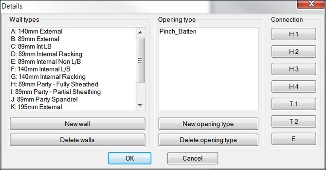
Wall types – Select a predefined timber frame wall types to edit.
New wall – Define a new timber frame wall type.
Delete walls – Select a wall type you want to delete.
Opening types – Select an opening type to edit.
New opening type – Define a new opening type.
Delete opening type – Select an opening type you want to delete.
Connection H1 to H4 – You have access to the different Corner details and edit it.
Connection T1 and T2 – have access to the two TConnection details and edit
Wall end E – define the wall ends of the different wall types.
How to Edit a Wall
- Select hsbWall \ hsbWallDetails \ Open Wall Detail Interface.

- The Details dialog box will appears.
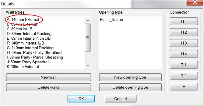
- Select an existing Wall out of the list.
- The wall type drawing will open.
- Do your changes and save the drawing with the command Save Detail.

How to Delete a Wall
- Select hsbWall \ hsbWallDetails \ Open Wall Detail Interface.
- The Details dialog box will appears.
- Select the Delete Walls button.

The Delete walls dialog box opens, select a wall type and then OK.
How to Make Corner Connections (See video 4:37)
Once you have defined some Walls your Details dialog box could look like this.
You now need to define all your corner connections, T-connections and the End-connections of your walls
- Select hsbWall \ hsbWallDetails \ Open Wall Detail Interface.
- The Details dialog box will appears.
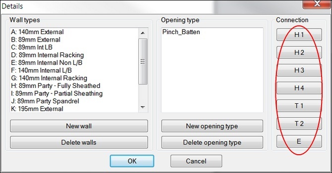
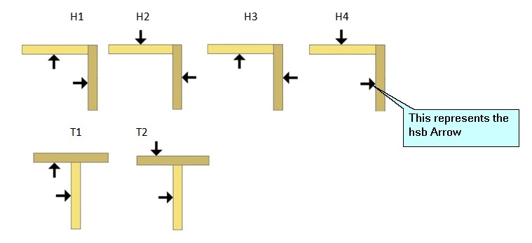
- Select a Connection (H1, H2, H3, H4, T1, T2 or E)
- The drawing will open with all the different wall types you have made, if this is not the case you will need to Update new details. (See Chapter Update new Details)
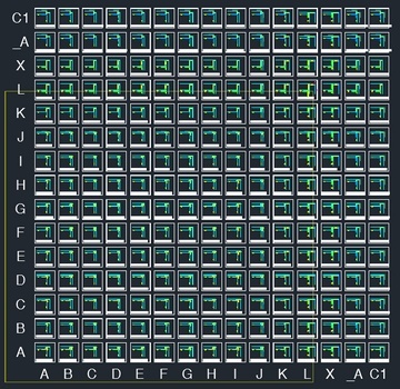
- Make your changes with the different tools provided. You can use the Autocad command’s to do this (Moverotate ect.)
- Do your changes; link the details to each wall and save the drawing with the command save Detail.

- Repeat these steps for all corner details,Tconnections and End connection (H1, H2, H3, H4, T1, T2 or E).
Dynamic sheet detail connections
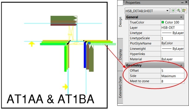
There is an option in the OPM (Properties bar) that you can use that allows you to make the sheeting dynamic.
When you draw a wall and you decide the sheeting has to be thicker in one of the zones you can add to your sheeting detail.
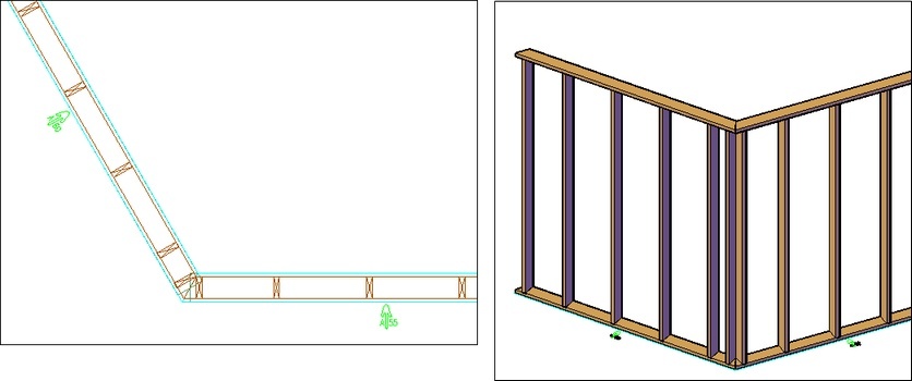
Angled End Wall Details
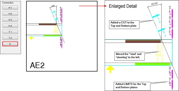
In hsbcad it’s possible to make corner connections of 15/22.5/30 and 45 degrees.
This example is made with the following functions: placed a cut, a Limit and use the command Move.
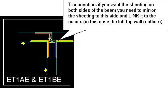
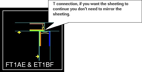
T connection
How to create Sheeting around opening
This command allows you to create specific sheeting around an opening.
To define Sheeting around opening run the command hsbWall\hsbWallDetails\sheeting around opening or select Opening Sheets in the ribbon.

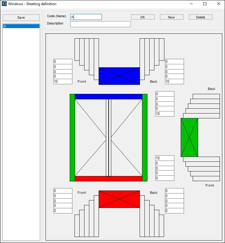
- This will open the Windows – Sheeting dialog box.
- Fill in a code and a suitable Description.
- Fill in the values you want in the front and back of each opening. (Blue=Top of the opening – Green= side of the opening – Red=Bottom of the opening).
- Select the Save button.
- To close this dialog box just select the X in the top right hand corner.
Example of were Sheeting around opening will be used.
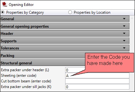
When you position an opening in your drawing with the command hsbWALL\Position opening you enter the code name of the sheeting detail in the Opening Editor Dialog box in the Structural general tab under sheeting.

How to use the Detail code table
This command allows you to select detail codes contained with your detail library. When you make a detail and you want to use this later on, to overwrite a certain beam or stud.

- Select Detail Code Table in the ribbon.
- This will open the hsbcad Detail Editor dialog box.
- Fill in the detail code you find in the left hand bottom corner of each detail drawing.
- Fill in an appropriate name that will give you a hont what the function is of the detail.
- Select the Save button in the top left corner of this dialog box.
Detail Code (Dialog box Explanation)
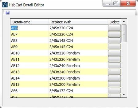
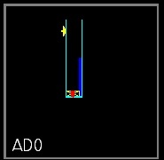
DetailName ‐ Fill in the detail code you find in the left hand bottom corner of each detail drawing (see picture ‘Detail’).
Replace With‐ Fill in an appropriate name that will give you a hint what the function is of the detail.
Example of were the Detail Code table will be used
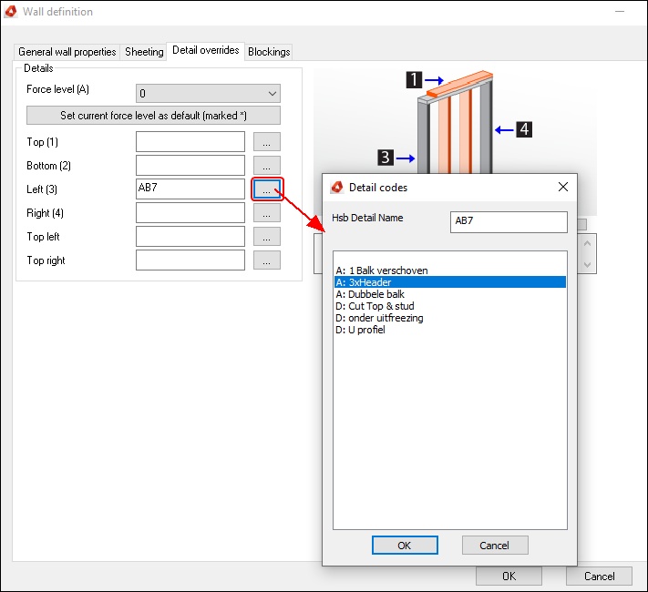
When you have made your details in your detail drawings and you use the command hsbWALL\Place Wall then you can use the Detail overrides tab to select a certain detail.
- Select the triple dots and select the detail you want to use.
How to Create an extra Beam
This command allows you to create/insert a beam in the Wall details.
To create a beam, define a New wall, run the command hsbWall\hsbWallDetails\Open Wall Detail Interface\Create beam or select Create beam in the Ribbon.

- Select the Create Beam function in the ribbon.
- This will open the Beam Detail dialog box.
- Fill in the necessary information.
- Select an insertion point in the detail drawing (center point of beam).
- Then select the direction of the beam.
- Select the Link Entities to Wall outline and link the beams to the Wall Outline.
- Save Detail changes
Beam Detail (Dialog box Explanation)
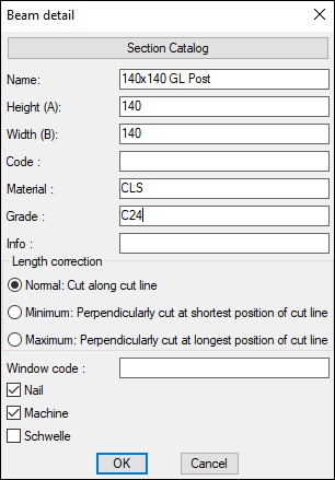
Section Catalog– You can select a predefined beam and import it to this dialog box.
Name – This is the name that you give to your Wall Type.
Height – Enter the Height
Width – Enter the Width
Code – Enter a certain code for the beam.
BLOCK_CHECK_START
This could be important if you want to use commands like saw, milling, drill, etc
BLOCK__END
Material – Enter a material name for the beam.
Grade – Enter a grade name for the beam.
Info – Enter additional information about the beam.
Normal: Cut along cut line – This refers to the information kept within the beam properties relating to how you will cut the beam. Normal is the default of the machine.
Minimum: Perpendicularly cut as shortest position of cut line – If there is an angle cut on the beam, the cut will begin at the closet point to the start point of the beam.
Maximum: Perpendicularly cut as longest position of cut line – If there is an angle cut on the beam, the cut will begin at the furthest point to the start point of the beam.
Window code – Allows you to enter a window code e.g. code name.
Nail – Is this beam to be nailed. yes/no.
Machine – Is this beam to be machined. yes/no.
Schwelle – Select if you want a Very bottom plate.
How to add an Extrusion profile
This command allows you to insert an extrusion profile in the Wall details.

- Select the Extrusion profile function in the ribbon.
- Select an extrusion profile in the Detail extrusion profile dialog box and fill in the necessary information.
- Select with left mouse button an insertion point (center point of beam).
- Select the direction of the beam.
- Select the Link Entities to Wall outline.
- Save Detail changes.
Beam Extrusion profile (Dialog box Explanation)
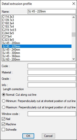
Name – This is the name that you give to your Wall Type.
Code – Enter a certain code for the beam.
BLOCK_CHECK_START
This could be important if you want to use commands like saw, milling, drill, etc.
BLOCK__END
Material – Enter a material name for the beam.
Grade – Enter a grade name for the beam.
Info – Enter additional information about the beam.
Normal: Cut along cut line – This refers to the information kept within the beam properties relating to how you will cut the beam. Normal is the default of the machine.
Minimum: Perpendicularly cut as shortest position of cut line – If there is an angle cut on the beam, the cut will begin at the closet point to the start point of the beam.
Maximum: Perpendicularly cut as longest position of cut line – If there is an angle cut on the beam, the cut will begin at the furthest point to the start point of the beam.
Window code – Allows you to enter a window code e.g. code name.
Nail – Is this beam to be nailed. yes/no.
Machine – Is this beam to be machined. yes/no.
Schwelle – Select if you want a Very bottom plate.
How to add an Extra Sheet

This command allows you to insert an extra sheet in a detail drawing.
- Select the Extra sheet function in the ribbon.
- This will open the Extra sheet dialog box.
- Fill in the necessary information or select the Catalog button.
- Select with left mouse button the start point.
- Select the end point.
- Select the Link Entities to Wall outline.
- Save Detail changes.
Extra sheet (Dialog box Explanation)
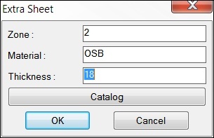
Zone – Enter the zone you want the extra sheeting to be, you need to select an existing zone. In this case you have a choice between zone 1 and zone 2.
Material – Enter the material name for the sheet.
Thickness – Enter a value for the thickness.
Catalog – Select this button if you want to import a new sheeting or select a predefined sheeting.
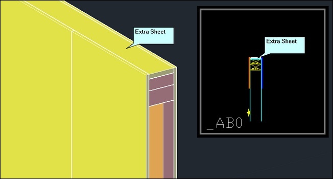
How to insert a TSL
This command allows you to have a TSL called every‐time this particular detail is cited.
- Select the TSL function in the ribbon.
- This will open the Detail TSL dialog box.
- Fill in the necessary information.
- Select the Link Entities to Wall outline.
- Save Detail changes.
Detail TSL (Dialog box Explanation)
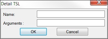
Name – Enter the TSL name.
Arguments – This reads an execution key which can be placed within a tsl e.g. to change colours of beams. This can change many different things.
How to insert Tools (Links to an external page)
How to insert a Set Limit (See video 8:16)
How to insert a Saw line
How to insert a Mill (Milling element)
How to insert a Drill (See Video 18:12)
How to Mill a beam (Milling Beam) (See video 14:00)
How to place a Cut (See video 16:15)
How to place Horizontal Blockings
Link Entities to Wall outline
This command allows you to link the new beams, sheets, milling or saw lines and so on to the detail it belongs to. If you don’t link the new entities (changes) to the detail or wall Outline your new entities (changes) won’t be saved in the detail.

- Select the Link Entities to Wall Outline function in the ribbon.
- Select with the left mouse button all entities / objects of the detail.
- Confirm with the right mouse button.
- Select with the left mouse button the Wall Outline of the detail.
- Confirm with the right mouse button.
- Save Detail changes.
Reset Wall Details
This command allows you to reset details to the origin status.
For example if you want to re‐use an existing Wall type Code you need to Reset Wall Detail

- Select the Reset Wall Detail function in the ribbon.
- Select the square which needs to be reset.
- Save Detail changes.
Update New Details in DWG
This command allows you to update details of newly defined walls. Already defined details of old walls won't be changed.

- Select the Upload New Details function in the ribbon.
- The update will automatically start.
- Save Detail changes.
Update Walls with new description
This command works automatically when you want to update the wall with a new description or have changed anything in your Wall detail and you go to your H1‐H2‐H3‐H4‐T1‐T2‐E, the changes are done automatically.

Save Detail Changes
This command allows you to save all changes in the detail drawing and the database.

- Select the Save detail Changesfunction in the ribbon.
- All the changes you have made have now been saved

