Essential Guide to Fasteners
The fastener assembly is a one dimensional collection of entities initially designed for the needs of glulam and Post & Beam Timberframe type construction.
There is the main component, which is typically the shaft of the fastener, with one or more subcomponents located either at the ‘head’ end of the shaft or at the ‘tails’ end.
Database driven Fastener Styles
An extensive database is already created that has several categories and allows filtering views based on previous selections.
As a style based assembly, the user must initially set up their styles.
To do so do the following:
- Select the Style Manager

- Right click on hsbcad Fastner Assembly Style \ New
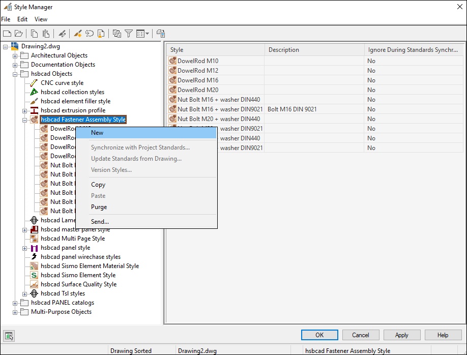
- Once you’ve given an appropriate style name select the Edit Style button on the right side of this dialog box.

The Fastener dialog box will open.
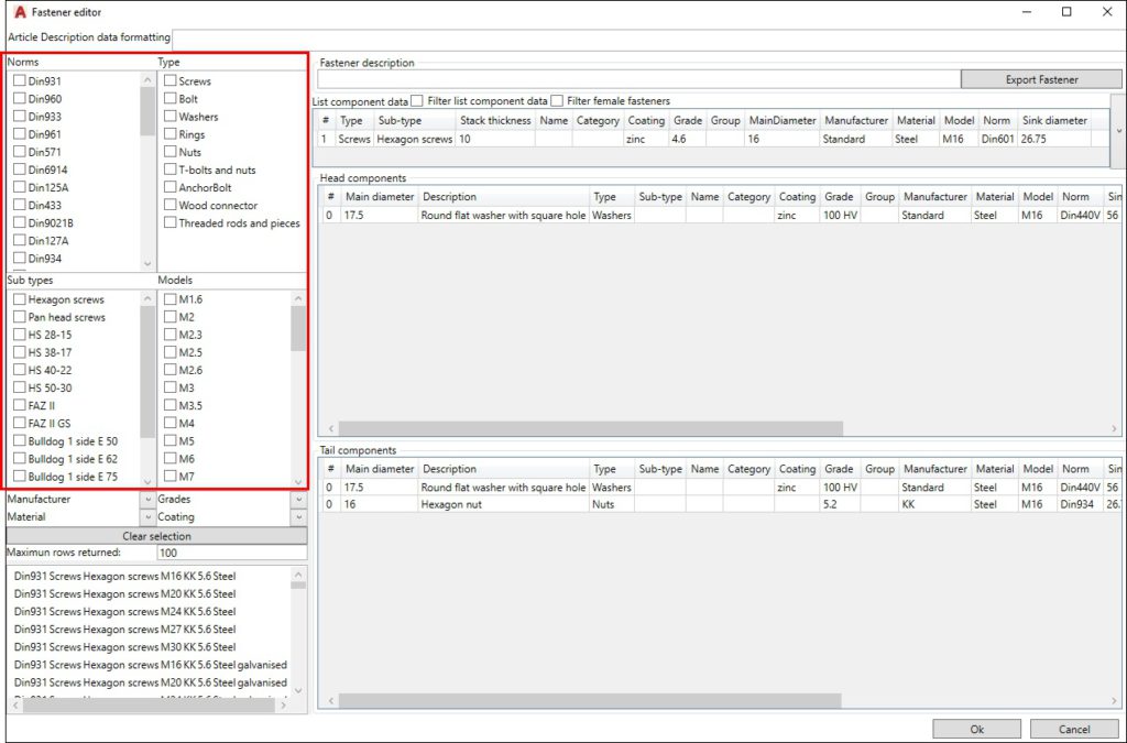
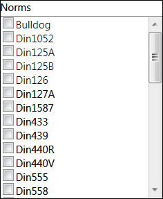
Fastener Norms
The International Standardization Organization, widely known as ISO, is an international standard-setting body composed of representatives from various national standards
organizations.
DIN, Deutsches Institut für Normung (in English, the German Institute for Standardization) is the German national organization for standardization and is that country's ISO member
body. In general, each country or economy has a single recognized National Standards Body (NSB).
The American National Standards Institute (ANSI) is the US NSB member of ISO.
Fastener Type
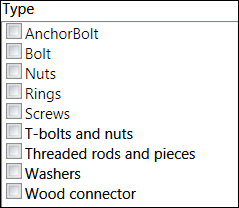
The second property, on which the database filters, is the fastener type.
Types include such items as Bolt, Nuts, Washers, Screws, etc.
This refers to the Primary Fastener component, typically represented by the single shaft of the fastener.
Once the user has selected a Fastener Type, the subsequent selection lists below are filtered to aid with selection of matching items.
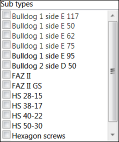
Fastener Sub types
The third property on which the database filters, is the Sub types.
Fastener Models
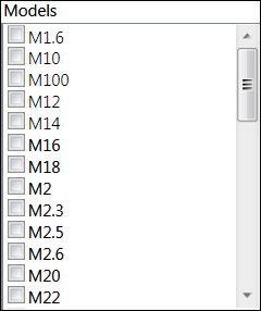
The forth property on which the database filters, are the Models.
This metric stud bolt to nut table is meant to help determine the correct size bolt or nut for your filtering.
Once you have filtered the requirements, drag and drop the hardware from the left side to the right side (main Shaft Components) of this dialog box.
The hardware can now be seen in the right hand side.
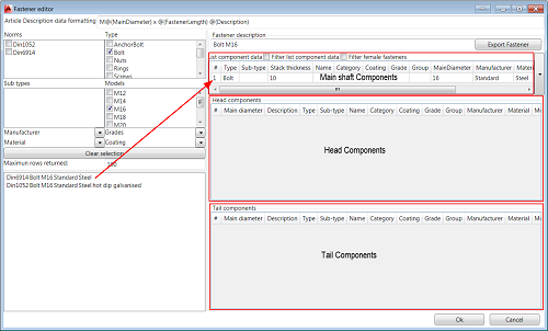
Do the same for the Head and Tail components.
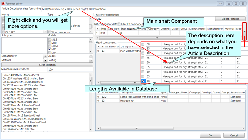
The main component (the shaft component) will have multiple lengths stored in the database, to see the different lengths select the pull down button (little arrow) on the right side of the Main Component, a pulldown wil appear.
Once the style is created, go back to your drawing and add a fastener to your drawing by doing the following
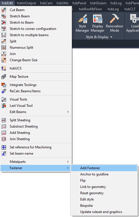
Add Fastener command
Once you have made your Fastener styles you can add these styles by Add Fasteners.
The command for adding a fastener is hsb_fa_add.
It can also be accessed from the hsbEdit menu under Fastener menu item.
A dialog with a single dropdown is called from which the user selects the Fastener Style to be inserted.
After a fastener assembly is inserted the user can view the properties in the OPM.
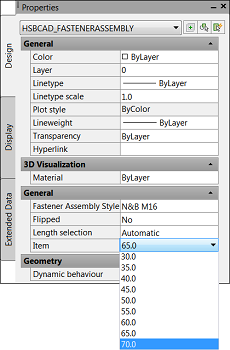
Under the General properties (OPM), the Object field displays the current product length of the fastener.
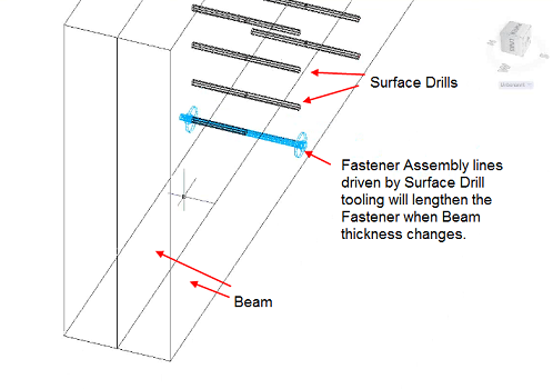
The length of the fastener assembly is controlled by the length of the fastener assembly guide line.
This assembly guide line can react to toolings, such as a Drill line and be manipulated and placed via TSL.
For example, if the host drill line through 2 ply beam is lengthened due to adding a ply or changing the thickness of the beam, the fastener assembly length will automatically be
adjusted. This is the standard behavior assuming the Length Selection property on the Fastener Style remains set to the default Automatic value. However, if the user changes the
Length Selection property to User Defined, a dropdown becomes active on the Object field allowing the user to manually override the product length selected from the database.
BLOCK_INFO_START
The automated lengthening of the fastener assembly line must be controlled by an hsb tool that can react to changes in the beam entity.
BLOCK__END
For example, the Free drill tool will not trigger an automated length adjustment of the fastener entity because it does not natively react to the beam.
If you attach the Fastener Assembly Guide Line to a Surface drill tool which reacts to the beam, then the fastener assembly guide line will automatically be adjusted.
Anchor to guideline
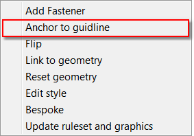
Anchor to Guideline is used to anchor fasteners along an existing Fastener Assembly Guideline in the drawing.
This command is hsb_fa_anchorto.
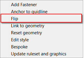
Flip
Simply swaps the orientation of the fastener along the axis of the shaft between head and tail ends and is typically done from the right click context menu.
This command is hsb_fa_flip.
Link to geometry
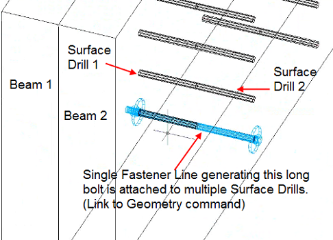
This allows the user to link a Fastener to one or more Fastener Guidelines.
An example would be congruent Surface Drills (hsbEdit\Edit beam\ Drillings\Drill in one beam) passing through multiple beams in and end to end fashion.
This command allows the user so attach multiple Fastener Lines to a single Fastener Assembly.
This command is hsb_fa_linkgeo.
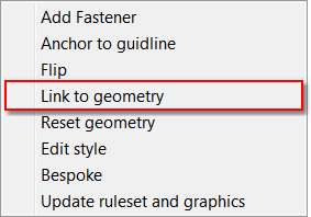
Once you have added a fastener to one of the Guidelines, select Link to geometry, select the Fastener Assembly and then the other guideline, the Fastener Assembly will extend
over the 2 beams.
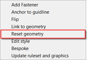
Reset Geometry
This removes the Fastener Assembly and its related Fastener Line from the geometry or tools.
This command is hsb_fa_resetgeo.
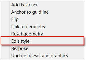
Edit Style
This opens the Style Manager to the selected Fastener Assembly Style.
This command is hsb_fa_editstyle.
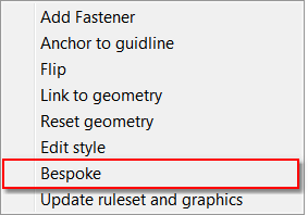
Bespoke
This allows the user to edit the list of lengths available for the style created.
This is only applicable for the primary component of the fastener (the shaft)
This command is hsb_fa_styleaddbespoke.
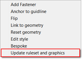
Update Ruleset and Graphics
This is an internal command that re-imports the graphic ruleset if it has been changed.
This ruleset controls the appearance of the fastener assembly, e.g. an anchor bolt with nuts, and washers, a standard hex bolt, etc.
This command is hsb_fa_importgraphicsruleset.
These tsl’s can be found in C:\Program Files\ITW\ITWhsbcad2014\FastenerAssembly
Do not change these TSL’s, will be overwritten when you update.
Fastener description
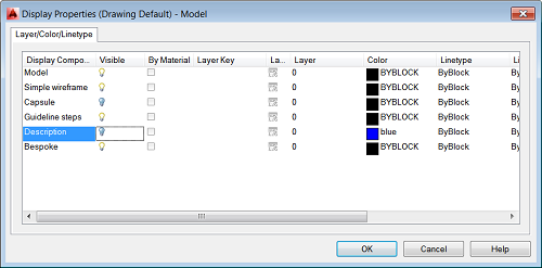
If you want a different description of the Fastener Assembly in your drawing you must fill in the Fastener Description in the Fastener Editor box.
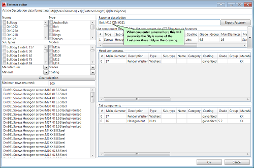

If you don’t want to see any description in the drawing you can hide this by right clicking the fastener Assembly\Edit object Display\ switch of the description using the light bulb.
Export to Excel
If you have used the Excel export before, do the following.
If you have been a regular user of the excel export you will know by now that once you have used the excel export a folder is automatically created in your hsbCompany\Excel called ‘’hsbReport’’.
This Folder contains 2 files, the excel template hsbReport.xlt file and the hsbReport.erp file.
This folder needs to be DELETED so the new template example can be used that we have made for you to export the Fasteners. (This contains the old example + an extra tab called Fasteners.)
If this is the first time you use the Excel export, do the following.

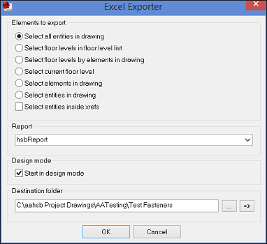
To export data to Microsoft Excel use the command Export\Excel Export from the hsbInOutput menu and select one of the options to preselect certain entities or collection of entities.
All available reports will appear in the dropdown list Report.
First users will only have one Report in the hsbReport.
The report hsbReport is a predefined report and will be generated when you run this command for the first time.
Select a report and press OK.
The program will export all selected entities as defined in the report and will automatically launch Microsoft Excel.
If you check the option Start in design mode the program will launch the Excel Report Designer.
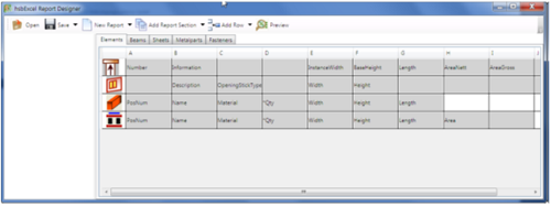
Select the Preview button (top right) and the command launches Microsoft Excel and creates an Excel Export based on the current report definition.
For more information on the excel export please refer to the hsbExcel document.

