Essential Guide to How to edit beams
This document will show you how to Edit beams.
If you want to edit beams you can use autocad commands to move, copy, and rotate any beam as well as specific hsb commands when you want to cut, split and stretch the beams. These commands can be found in the hsbEdit pulldown menu.
In general
Filter Z Coordinate
If you are moving or copying beams it is important to switch on Filter Z Coordinate in the hsbConsole so that when you move or copy a beam in the xy axis that the beam does not move in the z axis (i.e. if you move a beam by picking osnaps the beam could move in the z direction without you noticing it in the xy view).
Contact Surface
When you use some of the hsbEdit commands to stretch beams there is a Contact Surface created, this is a circle when viewed in 3d or looks like a line in plan. The Contact Surface is a link between 2 beams i.e. if one of the beams is moved the other may move also so that both beams still end when they meet, they do not overlap or stop short of each other.

Edit beams
Tools
Tools for editing beams can be selected from the hsbEdit drop-down menu and also by selecting beam(s) and accessing the menus by right-clicking on your mouse.

Cut beam
The cut beam command will allow you to select beam(s) to be cut and define a plane to cut beams by entering an autocad plane or selecting points.
BLOCK_ALERT_START
If you cut the beam in half, the beam will still have the original dimensions, so be careful in using this function to change the beam size (use ‘Change beam size to this).
BLOCK__END
Stretch beam
Select hsbEdit\Stretch Beam when you want to stretch a beam. This can mean that the beam becomes shorter or longer, depending on the points that are picked.
Stretch to beam
Stretch to beam is used where you want to stretch beams to meet another beam.
- Select hsbEdit\Stretch To Beam.
- Select the beam(s) to be stretched.
If necessary turn on automatic on the InteliSelect dialog and customise your settings to suit.
- Secondly select the beam that you want the first beams sent to.
Stretch to corner configuration
Stretch to corner connection is used when you want to stretch 2 beams to meet at a corner connection.
The 2 beams selected will extend until they meet at a point.
Select hsbEdit\Stretch to corner configuration.
Select the 2 beams to use for a corner connection.
Stretch to multiple beams
Use Stretch To Multiple Beams when you want to stretch a beam to 2 or more beams, the first beam will be stretched to whichever of
the other beams is closer even if you move around the beams afterwards.
- Select hsbEdit\Stretch To Multiple Beams
- Select the beam to be stretched, and then
- Select the beams you want to be included in the beams to be stretched to.
The first beam will be stretched to the nearest beam of your group of beams.
If you make a different beam from your beam group closer to the first beam, your first beam will now stop at the closest beam.
Split
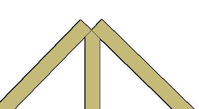
The split beam command will allow you to select beam(s) to be split and define a plane to split beams by entering an autocad plane or selecting points.
DefaultThe default method for splitting beams is to pick 3 points on screen, the third point can be perpendicular to the current ucs (by pressing enter).XYAllows you to pick a point on screen and use the XY plane at this point to split the beam(s).YZAllows you to pick a point on screen and use the YZ plane at this point to split the beam(s).ZXAllows you to pick a point on screen and use the ZX plane at this point to split the beam(s).ObjectThe object method will allow you to split a beam that intersects with a Roof Plane, hsbPanel or a Polyline.
Numerous split
Numerous split will allow you to split a beam into numerous sections where it intersects with the first beam selected.
- Select hsbEdit\Numerous Split
- Select the beam to be split.
- Customise your settings on the Numerous Split dialog.
- Select the beam(s) you want to use for splitting.
Join
Join beams will allow you to join 2 beams into 1 beam; the two beams have to be rotated at the same angle.
The 2 beams do not have to be the same width or height but when you select the 2 beams the resulting beam will have the same width and height as the first beam selected.
- Select hsbEdit\Join
When prompted to select objects, select the 2 objects to be joined (remember first object gets preference for new beam size).
Change beam size
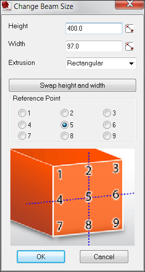
Change beam size will allow you to change the width/height of beams and also control the base point while changing the beam size.
You can also change the size of a beam through the autocad properties dialog, but you can’t control the base point if you chose this method.
- Select hsbEdit\Change Beam Size
- Select the beam to be changed.
- On the change beam size dialog
- Select the reference point and enter a new width and height.
hsbUCS
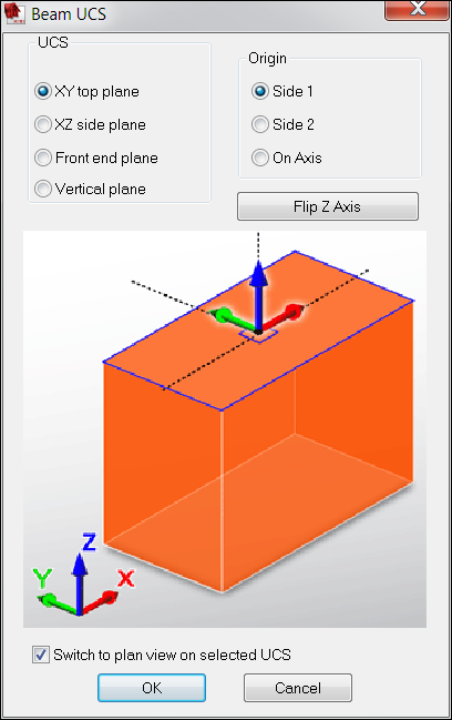
Select hsbEdit\hsbUcs, to set the Beam UCS, will let you change your UCS view.
Type ‘Plan’ in the command line and right click to enter, this will go to the view you have just chosen.
Integrated tooling
This command allows you to use an object as a tool (e.g. cut through another beam). This information will be read from the Machining (e.g. Hundegger, Weinmann).
To do housing on two crossing beams you don't have to use an extra tooling. You can use this command.
Generally you use a dummy beam for doing Integrate tooling.
BLOCK_INFO_START
This can only work with bounding box shapes (squared and rounded profiles).
This command can also be used to link other hsbcad Tools (i.e. drill’s and some tsl’s).
BLOCK__END
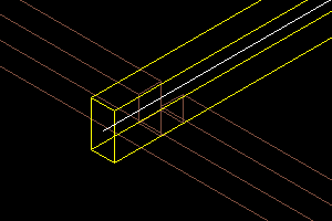
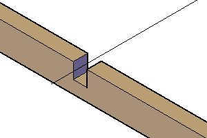
- Select the hsbEdit pull down menu and select the Integrated Tooling command.
- Select an object (Beams, elements, opening), enter.
- Select the tool (In this example we have selected another beam that we have made a Dummy)
- Confirm with Enter.
You can identify the object with a tooling when it has a black line.
This line symbolizes the tooling.
If you delete the line the tooling will be removed from the object.
You can edit the tooling in the properties bar, first select the tool and then change the data in the properties bar.

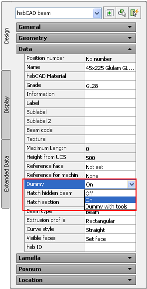
Dummy Beam
A dummy is usually an hsbObject, except the dummy can't be numbered and therefore can't be displayed in an excel list (stock sheet).
In addition, the dummy doesn't have machine data (e.g. for a Hundegger or Weinmann machine).
The dummy is only visible in a 2D-wireframe mode. (see AutoCAD))
HSB_Hidedummies : allows you to hide the dummiebeams.
HSB_Showobjects : view the dummiebeams.
