Essential Guide to Revit® | BIM drawing rules
When you start a BIM project with other companies, where every company makes his own BIM drawing you first need to make really good agreements because it is very important that every company you work with got the same drawing rules.
One of those agreements are the 0 points.
In Revit you got 2 difference 0 point:
- Project Base point.
- Survey Point.
You still can change both points during the drawing process if you want. But it is advisable to put the points on the right position before you start modelling.
The reason is because if you want to share your BIM project with other companies it is necessary that you and the companies got the same Project Base Point and Survey Point.
If you want check on which coordinates your points are.
You go to the light bulb.
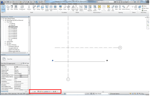

After you pressed on the Light Bulb you will see that the screen turns pink.
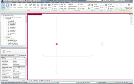
You also see that a circle object appears with a cross in it, this is the Project Base Point and the Triangle object is the Survey Base Point.
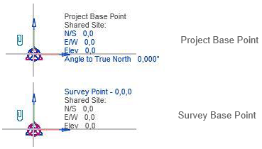
To select one these Base Point you must select it with your cursor.
BLOCK_INFO_START
If you press Tab during the movement with your cursor over the Base Point, you can easely switch between the Base Point.
BLOCK__END
If you press on the light Bulb, your Base Point will disapear. To keep these Base Point both visible you must select the Base Point, press the right mouse click and choose for “Unhide in view”. To make sure you don’t move the Base Point accidentally you can pin the Base points.
- The Survey Point in Revit is espaccialy for the 0 point in a IFC or IFCzip files.
- If you go to the Tabb Manage, you can change difference settings for the location, position or coordinates.

There are several ways to set up your project in terms of coordinates, position, and north.
The main preference way is to put the coordinates before modelling in the right settings.
0 point indicator
In the national BIM manual they advise to put the 0 point indicator on the 0 point to make. To facilitate coordination between models.
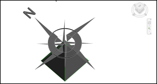
There are different ways to insert different type of files in to Revit.
1. DWG file.
2. IFC file.
3. Revit file.
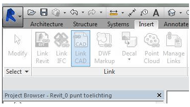
The preference goes to link a DWG file because it has the smallest file format.
If you link an IFC file into Revit, Revit will make it in the background a RVT file. That means that the Drawing will be very heavy to work with.
The link has the advantage that the Survey Point can be used to select:
- Auto - Center to Center.
- Auto - Origin to Origin (Project base Point).
- Auto - By Shared Coordinates (Survey point).
If the common 0 point (Survey Point) doesn’t match with the Project Base Point, and the True North doesn’t match with the Project North.
When you change the the Survey Point and True Point, the 0 point indicator will change automatically.
If you go to “Insert Tab” and select “Link Cad”.
You will see the following screen.

Positioning:

Imports units:
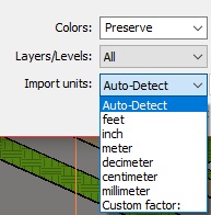
When you insert in a 3D view, it advisable to choose for:
- Auto - By Shared Coordinates.
- And place it on level 00.
If you press on the light Bulb again you will see that the 0 point is been placed correctly.

It is recommendable to import the linked DWG files through “manage link”
This will prevent deleting the linked file for errors.
And to pin the 0 point you won’t accidentally move the point.
Changing Common zero and True North
When the common 0 point (survey point) and the True North or not correct you can easily change this.
Step 1. Go to:
- Tab Manage.
- Select Coordinates.

Step 2. Choose for specify coordinates at point.
Step 3. Click on the Common 0 point and put the (XYZ) coordination on 0,0,0.
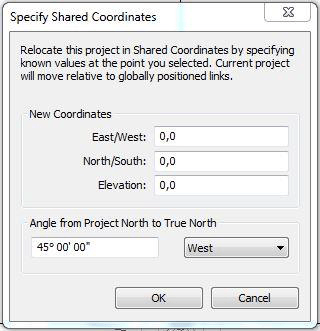
Step 4. If the True North isn’t right you can change this also.
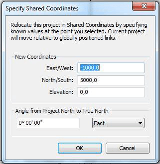
When the coordinates say for example you put the True North on 45 degrees you will see the following results.
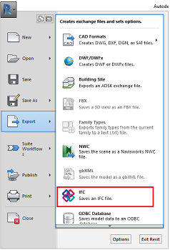
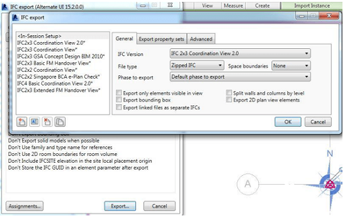
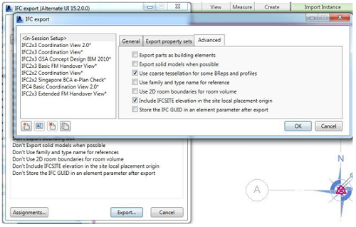
To Export the 0 point with the IFC export you must set this in the IFC mapping.
Go to:
