How to draw openings in hsbWalls (Video)
Opening Definition
The function of this document is to provide information on how to Place an Openings in hsbcad.
You can insert Openings, Doors and Windows in hsbWalls.
When you add openings in hsbcad, you have the option to select an ACA style to use for the Window/Door to give the doors some style.
This is only an option if you are using hsbdesign with Architectural Desktop and you have defined an opening style.
BLOCK_CHECK_START
ACA style: aecstylemanager\in your Template file create a new door and window style in the Style Manger \ architectural objects.
BLOCK__END
When inserting openings it is important that the opening goes on the correct group, as you could accidentally put a ground floor window on a first floor wall.
Before you insert an Openings
Before you start placing an opening in a wall, make sure that the correct Floor Group is selected for the opening you are inserting.
And you need to draw a wall before inserting an opening.
Extra information on how to change the colour or text size can be found in the follow document. How to change text opening parameters

How to Place Opening
Run the command hsbWall\Position Opening or select the following icon on the toolbar.

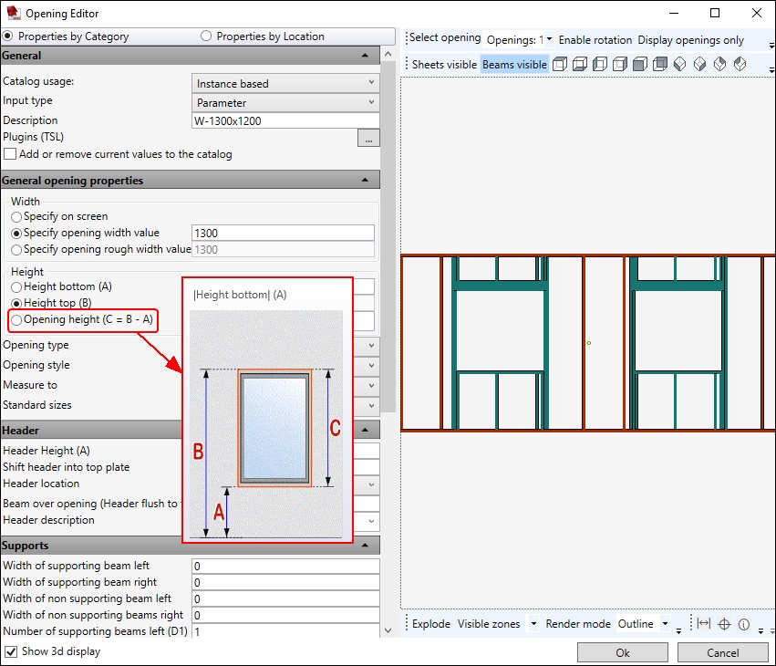
The Opening Editor Dialog box will appear, fill in the information to define the opening.
On the right hand side of the dialog box you will see the graphic representation of the opening(s) you are inserting, this will change when you insert values on the left hand side of this dialog box.
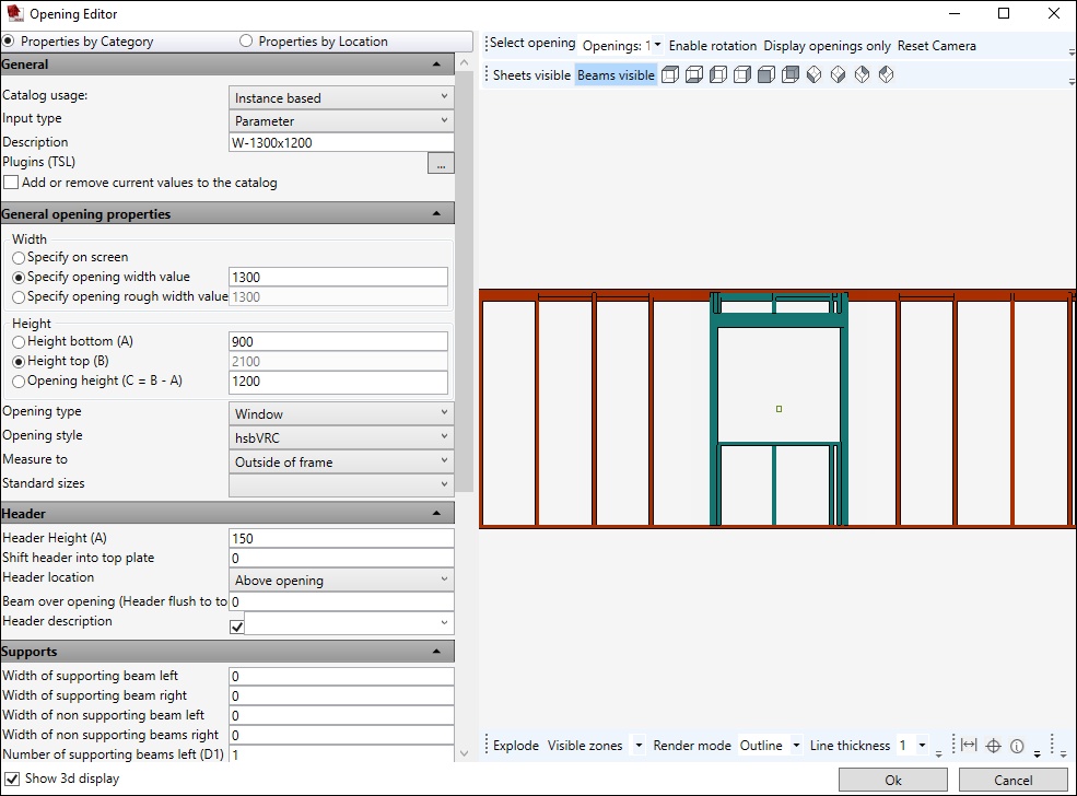
Properties by Category - Properties by category means that the properties are grouped by category in the same order as they are in the ACA’s OPM (Object properties Manager)
Properties by location - When you select a point on the openings graphical representation (right hand side of this dialog box) you will see the properties that correspond to the location you have clicked on.
The properties are grouped into five locations around an opening: the header (top), the sill (bottom), left, right and centre.
- Select any point around the opening and you will get the opening values you have entered.
BLOCK_WARNING_START
In case all tabs are collapsed you can right click on a tab and Expand all tabs.
BLOCK__END
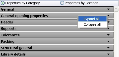
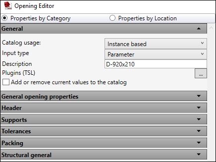
- Select the option Properties by Category.
General Tab
Catalog usage
- Select one of the 5 options.
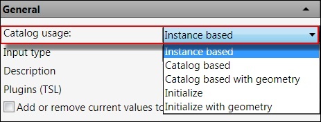
Instance based - You can start a new opening from scratch.
Catalog based - You can select any previously saved doors/openings/windows (stored in the Catalog).It will not read the General opening properties values but it will read all the rest of the values.
You can edit the General opening properties.
Catalog with geometry - You can select any previously saved doors/openings/windows (stored in the Catalog).
You CAN’T change any values.
Initialize - You can select a predefined opening (stored in the Catalog); It will not read the General opening properties values but it will read all the rest of the values.
You can still change all the values.
Initialize with geometry - You can select a predefined opening (stored in the Catalog), but still change all the values.Input Type
- Select one of the 3 options
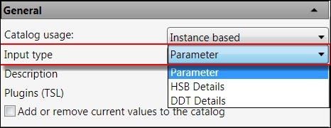
Parameter - Select if you want to enter the parameters of the openings. This is de default setting.
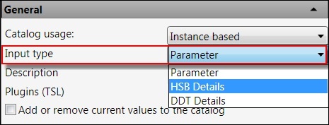
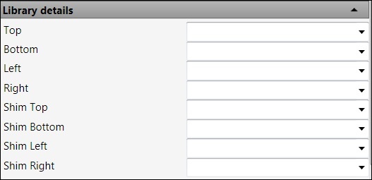
HSB Details - Select if you want to input hsb Details, like library details (Overrides), more information in the next Chapter.When using the HSB Details, the Library details tab will appear. (Very bottom of this dialog box)

This is an override where you can use a detail from another opening detail defined in the hsbDetails.
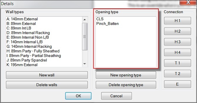
Enter the name of the opening detail and the opening will automatically use this detail as defined for the particular wall for the timbers at the Top, Bottom, left, right of an opening. You can only enter this override in conjunction with the Detail value above.WHERE TO FIND THE NAMES TO ENTER IN THE ABOVEhsbWALL\hsbWALL Detail\Open Wall detail interface\select an Opening type, in this case we have made 2 opening types in this example:CLS and Pinch_Batten.
DDT Details - Select if you want to input DDT Details, like shim details.
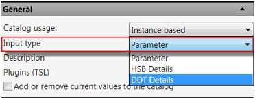
When using the DDT Details, the Library details tab will appear with the extra functions (shim details).These fields are for information only, they display the shim details that are being used for a specific style that have been applied.
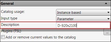
Description
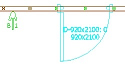
This is the text that will appear in the opening in model space (e.g. D-920x2100)
Plugins (TSL)
You can attach a TSL to the opening.
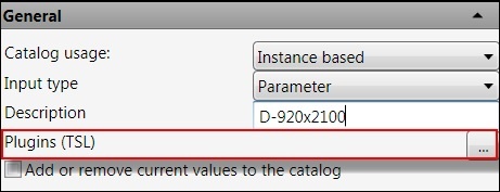
- Select the triple dots and the Opening Plugins dialog box will appear.
You can select a predefined TSL in the Catalog or add a new entry, by selecting the Add button.
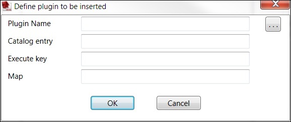
The Define plugin to be inserted dialog box will open, select the triple dots and select the TSL you desire to insert in the opening.
Add or remove current values to the catalog Chapter
Once you have filled in all the information about an Opening/Door or window you can save this into a Catalog and load them on another occasion.
Or you can Remove an existing entry.
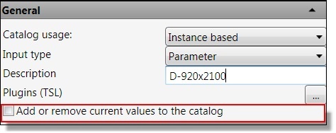
- Select the Add or remove current values to the catalog button.
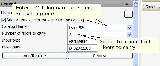
The General tab will change.
Enter a Catalog Name and entered the Number of floors to carry.
- Select the Add/Replace button.
To remove an Entry select the Remove button.
Number of Floors to carry - This is a value used by rules to use different opening framing data based on where the opening’s host element is located in the model.
For example, if the building has 4 levels and the opening is in a wall element on the 2nd floor, the framing style selected will be the one with 2 floors to carry.
BLOCK_CHECK_START
Note: It is always assumed that a roof is also carried, so this property refers to floor diaphragms located vertically higher than the wall with the opening.
BLOCK__END
BLOCK_WARNING_START
Important: When you Remove an Opening that has an amount of floors attached, you need to Remove the same amount of times out of the catalog.
BLOCK__END
Maybe an example of this: If you have added a style Door 920 with number of floors above 1,2,3.
- A user in order to delete these entries must select the style name Door 920 then select Number of floors to carry 1 and then press delete.
This step must be repeated selecting number of floors above 2 and 3.
General Opening Properties tab
In this tab you enter the information that defines the geometry of the opening.
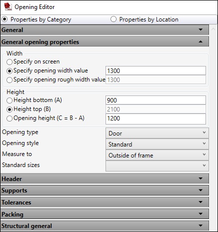
Width
Specify on screen – Select if you want to specify the opening width on your screen.
Specify opening width value - Select if you want to specify a fixed value.
Specify opening rough width value – If you have an Architectural Desktop opening style already defined (see Style manager dialog box on the next page), and the Measure to is set to Inside of Frame this will show the dimension of the opening + ADT frame width, in this case the frame width is 30.
Height
Height Bottom (A) – Enter the height from current groups floor height to the bottom of the opening. When you scroll over the text a picture will appear.
Height Top (B) - Enter the height from current groups floor height to the top of the opening. When you scroll over the text a picture will appear.
Opening Height (C = B-A) – Enter the height from the bottom of the opening to the top of the opening.
BLOCK_CHECK_START
When you scroll over the text with brackets, a picture will appear.
BLOCK__END
Opening Type
- Select an hsbOpening type from here. (Opening-Window-Door).
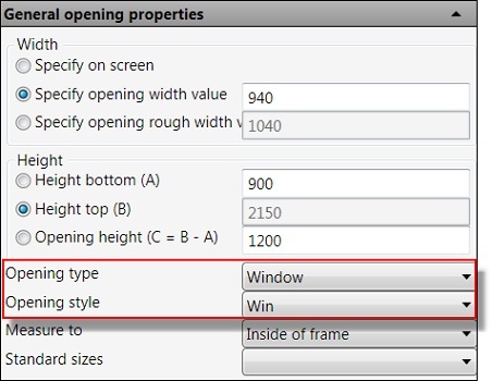
Opening Style
If you have an Architectural Desktop opening type already defined, then you
can select that style from here and you will see the opening style in model space.

BLOCK_CHECK_START
NOTE: When you select Opening in the Opening type you will not get the option Opening style but Shape will appear.
BLOCK__END


Measure to
- Select if the measurements are from the Outside of frame or Inside of frame.
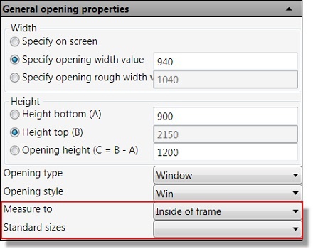
Standard sizes
Standard sizes ensure consistency by allowing designers to select sizes from a predefined list specific to the window style.
You can also enter custom sizes when you add or modify individual windows.

Rise (D)
Enter the height of the Radius.
This works only with Openings and Windows in combination with Trapezoid/Peak Pentagon (Shape).

Header tab
In this tab you enter the information that defines the header.
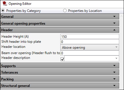
Header Height (A)
Enter the height of the header that you require.
This will give you a block of timber to suit the width of the studs used in conjunction with the header height that you enter.
BLOCK_WARNING_START
Important: When using this function without using the header description, the header description should not be filled in (it has to be blank) otherwise the header height is not applied.
BLOCK__END
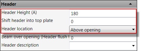
Shift Header into top plate
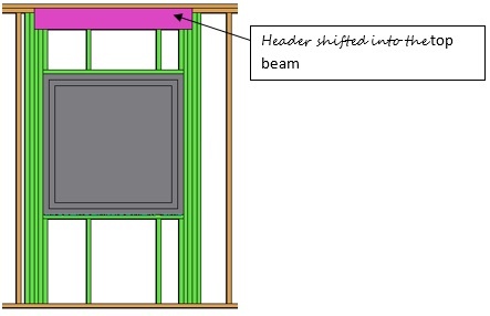
Enter a Value (mostly the thickness of the 2nd top beam).
This will shift the header beam into the 2nd top plate.
BLOCK_WARNING_START
Important: You need to Mark Header location Below Plate for this function to work.
BLOCK__END
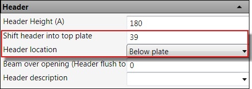
Header location
This has 2 options:
Above Opening – Select this if you want the header placed directly above the opening.
Below Plate – Select this if you want the header placed directly below the top plate.


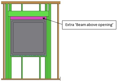
Beam over opening
Enter a value and an extra packer will be added above the opening.

Header Description
This has two methods of use:
- If you have entered a value in the Header Height (A), then you can enter a description of the header, which will appear in the manufacturing drawings.
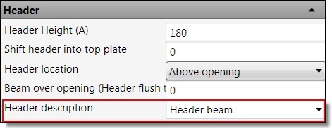
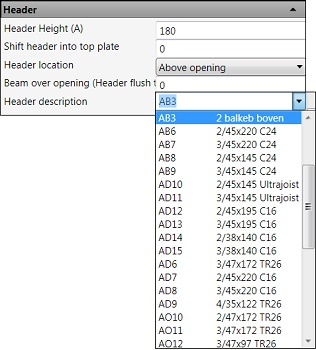
Or you can enter an hsbDetail code (e.g. AB3)
This will then create the header as detailed in the hsbDetails for the wall type in question.
Select the pull down button and the Detail code dialog box will open, select one of the codes names in the list and the name will appear in the button.
This will then create the header as detailed in the hsbDetails for the wall type in question.
BLOCK_WARNING_START
Important: When NOT IN USE please make sure it is Blank (otherwise the header height is not applied).
BLOCK__END
Support Tab
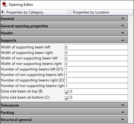
In this tab you enter the information that defines the supporting and non supporting beams.
Width of beams
Width Of supporting beam Left - Enter the Width (0=Default) of the Supporting studs at the left of the opening here. Leave Blank if these are the same as the beams which are specified in the walls details.
Width Of supporting beam Right - Enter the Width (0=Default) of the Supporting/Non-Supporting studs at the right of the opening here. Leave Blank if these are the same as the beams which are specified in the walls details.
Width Of non-Supp beam Left - Enter the Width (0=Default) of the Non-Supporting studs at the left of the opening here. Leave Blank if these are the same as the beams which are specified in the walls details
Width Of Non-Supp Beams Right - Enter the Width (0=Default) of the Non-Supporting studs at the right of the opening here. Leave Blank if these are the same as the beams which are specified in the walls details
Number of beams
Number Of Supporting Beams Left (D1) - Enter the amount of Cripples/Trimmer Studs that you require at the left of the opening.
Number Of Non-Supporting Beams Left (E1) - Enter the amount of King Studs that you require at the left of the opening.
Number Of Supporting Beams Right (D2) - Enter the amount of Cripples/Trimmer Studs that you require at the right of the opening.
Number Of Non-Supporting Beams Right (E2) - Enter the amount of King Studs that you require at the right of the opening.
Extra side Beam
Extra Side Beam At Top (B) - Enter the width (0=Default) for the stud to be used, this will put an extra stud over an opening at the side of the supporting studs. (If you leave it blank it will automatically take the beam size of the studs).
Extra Side Beam At Bottom (C) - Enter the width (0=Default) for the stud to be used.
This will put an extra stud under an opening at the side of the supporting studs. (If you leave it blank it will automatically take the beam size of the studs).
Tolerances tab
In this tab you enter the information that defines the Tolerances of the opening.

Packing Tab
In this tab you enter the information that defines the packers.

Packing
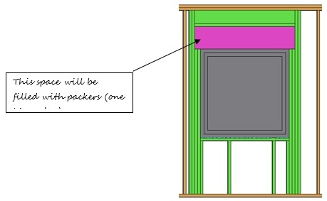
Packing Max Height - Here you can enter the maximum height between the header and the opening so it can be packed with packers (e.g.306mm).
Packer Thickness Over Header - Enter the height of the packer that is placed over the header, it is placed between the Non Supporting Studs. Minimum 5mm.
Packer Thickness Under Header - Enter the height of the packer that is placed under the header, it is placed between the Non Supporting Studs. Minimum 5mm.
Packing description - Text Filled in which is a description of the packing can be determined.
Structural general Tab
In this tab you enter the information that defines the extra packers, sheeting.

Extra packer Under Header (L)
Enter the height of the timber used as a packer directly beneath the header if using the header below plate option.
This packer sits between the Supporting Studs.
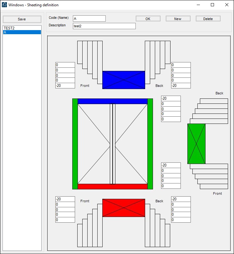
Sheeting (enter code)
Enter the code of the sheeting detail. Call upon predefined sheeting details - See 003-hsbWALL Details and define\ Opening around sheeting for more information.
This code needs to be Alphabetical and not numeric.
BLOCK_WARNING_START
Important: When NOT IN USE please make sure it is Blank, otherwise it will not generate.
BLOCK__END
WHERE TO FIND THE CODE TO ENTER IN THE ABOVE
hsbWALL\hsbWALL Detail\ Sheeting around Opening, in this case we have called it A.
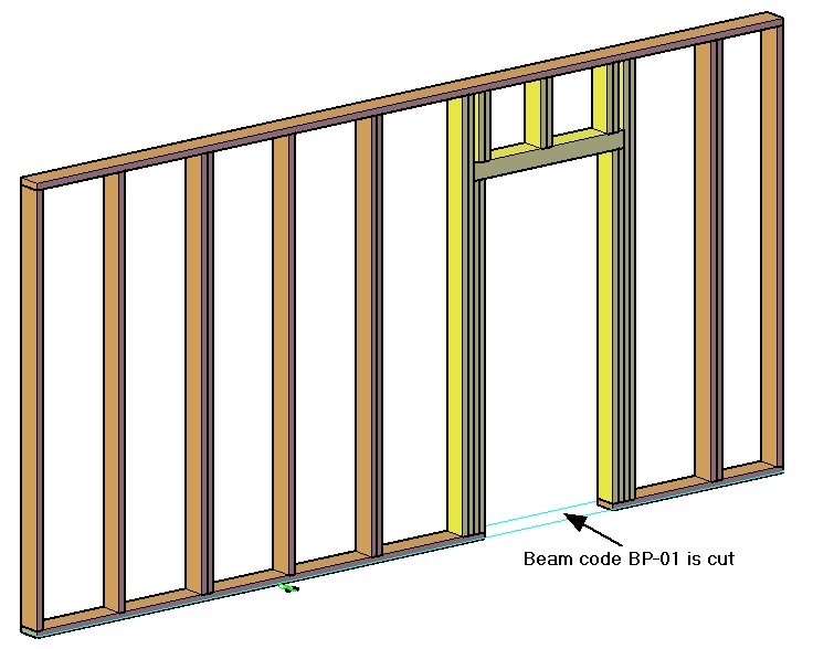
Cut bottom beam
Enter the code you have given the bottom beam. If you specify a balk code for a bottom plate in the hsbDetails, you can then enter the balk code here and the timber will be cut out underneath the opening.
BLOCK_INFO_START
Attention: The code can have multiple letters OR use *
BLOCK__END
Extra Packer Under Sill Jacks (K
Enter the height of the timber used as a packer under openings, sitting on the bottom plate between the Supporting Studs.

Opening Editor Right hand side
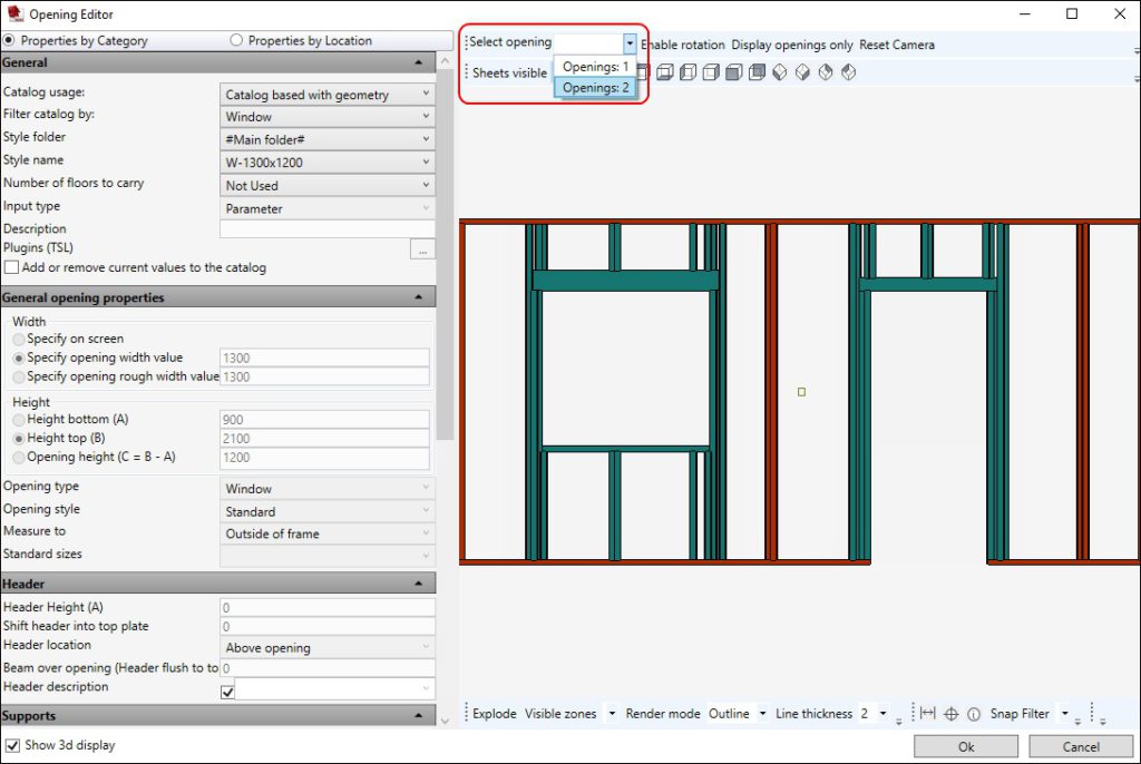
You can scroll in the graphical representation on the right hand side of this dialog box.
Select opening
Here you can see how many openings you have in your hsbWALL.
The properties on the left hand size change depending on the opening that is selected.
Enable Rotation
- Select and it will prevent you from rotating the image (graphical representation).
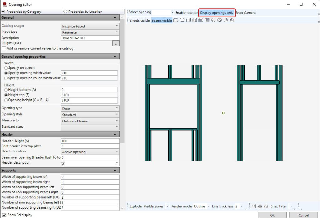
Display openings only
This will show you the opening beams only.
Reset Camera
Sets the view in it’s original state.
Sheets visible
Allows you to view the sheets.
Beams visible
Allows you to see the beams in the hsbWall.
Preset Views
You can select predefined standard orthographic and isometric views.
Explode
This explodes the sheeting (sets the sheeting separate from each other)
Visible zones
You can deselect the sheeting zones.
Render mode
You can select between Solid/Edge/Outline.
Line thickness
Sets the thickness of the lines around the beams.
How to change text opening parameters (video)
More information can be found in the following documentation How to Customize text opening parameters

