How to draw Planes
The function of this document is to provide information on the creation and editing of hsbPlanes.
A hsbPlane is a horizontal/sloped surface that can be used to project hsb entities to (walls) or used to create hsb entities on the plane (floors, roofs).
There are different ways in which to create planes depending on what you are going to use the planes for.

Create hsbPlanes
Add Icons + Generate Planes – Is used to create roof planes.
Draw Plane – Is used to create a plane that can be used for any plane (Floor, Roof).
Copy Roof Plane Down – Is used to create a plane from another plane.
Define Floor Panel Area – This is the same command as Draw Plane.
Dormer – Is used to create a Dormer Roof (Roof Plane).
Modify hsbPlanes
Merge Roof Planes – Is used to merge multiple planes together.
Subtract From Plane – Will allow you to subtract an area to an hsbPlane.
Add To Plane – Will allow you to add an area to an hsbPlane.How to create a hsbPlanes
You have three ways to design a roof
- Enter height at eave
- Enter wall and plate height (USA)
- Use profile
Create hsbPlanes
Add Icons - Enter height at eave - Enter wall and plate height (USA) - Use profile

Use the add icons and generate planes to create roof planes.
The add icons command will allow you to add an icon for each side of the roof plane.
You will specify the height were the plane meets the wall icon, the slope of the icon etc.
You can assign information about the roof geometry to walls or rather to outlines of areas.
The arrow of the roof icon always points perpendicular towards the ridge.
To Add Icons.
- Select hsbPlanes\Add Icons.
Enter height at eave
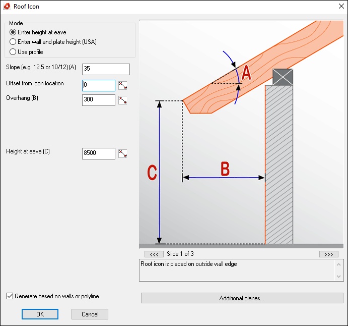
Slope - enter the slope in degrees (i.e. 25°) or as relation (i.e. 10/12)
Wall offset - the wall offset is the distance of the icon to the outline of the wall in direction towards the ridge.
Overhang - the overhang describes the distance of icon location to the eave / to the edge of the panel. The wall offset will be subtracted.
Height at eave - defines the height at the eave of the roofplane
Generate based on walls or polylines – Select this options, when you have drawn a closed polyline you only need to select this polyline and place the Roof icon where you want and all icons will be placed automatically.
Enter wall and plate height (USA)
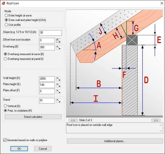
Slope - enter the slope in degrees (i.e. 25°) or as relation (i.e. 10/12)
Wall offset - the wall offset is the distance of the icon to the outline of the wall in direction towards the ridge.
Overhang - the overhang describes the distance of icon location to the eave / to the edge of the panel. The wall offset will be subtracted.
Wall height - the wall height up to the bottom face of the plate.
Plate height - the height of the plate. Note: this option is used to calculate the roof plane, it is not used to define the real shape of the plate in model.
Plate offset - the offset of the plate from the wall outline.
Stand - the stand is the distance of the base of the birdsmouth to the top of the rafter, measured plum or perpendicular to the roofplane.
Stand calculator - The stand calculator is a tool to calculate the stand from given values. The user can specify the calculation mode.
Additional Planes - opens the dialog to define additional planes
Use profile

One can define a polyline which is representing the section of the roof plane and assign it as profile to the icon.
You can also use a roof section created by the section wizard.
BLOCK_CHECK_START
Note: The polyline must be drawn in WCS and constantly rising in the positive xy-direction.
If you want to define a multi sectional roof on an existing drawing and the polyline would be rising in the negative x-direction you must mirror this polyline in order that it is constantly rising in the positive xy-direction.
BLOCK__END
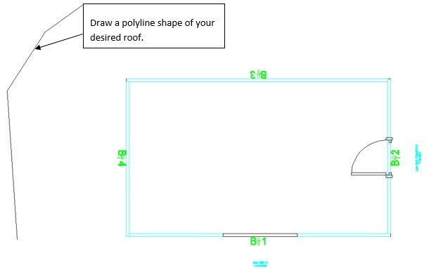
- Draw a polyline shape in plan view and set your UCS in world.
- Select hsbPlanes\Add Icons\Use profile, select the Generate based on walls or polyline button.
- Select OK, select the polyline you have just drawn and then
- Select all the Elements (Walls) in one go or one by one.
The roof icons will appear in your walls and place your roof symbol.
The roof has taken the shape of your polyline.
Wall offset - the wall offset is the distance of the icon to the outline of the wall in direction towards the ridge.
Groups Icons

You can set the order of the roof icons.
If you inserted the roof icons in one turning direction you don't have to use the command Group Icons anymore.
The manual grouping is redundant if you enable the option Generate based on walls or polyline when adding the icons.
Generate Planes

You can generate the 3D-Model of the roof planes.
When all icons are placed and grouped, one can select the roof symbol to start the generation of the roof planes
Draw Plane

Draw Plane will allow you to draw a horizontal/sloped plane by selecting points or convert a 2d/3d polyline to an hsbPlane.
- Select hsbPlanes\Draw Plane.
- Select if you want to Create Horizontal Plane. If you switch off create horizontal plane, you can select a closed polyline to convert it to an hsbPlane.
- Enter a code and color for the plane.
- Select OK and either pick the points for the plane or select the polyline to be converted to a plane.
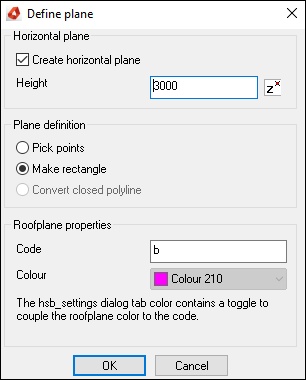
Create horizontal plane - creates a horizontal plane in the designated height.
Height - defines the height for a horizontal plane.
Pick points - one can pick points to determine the shape of the roof plane. The resulting plane will be projected to the height given in Height if the option Create horizontal plane is not disabled.
Make rectangle - creates a rectangular roof plane. The resulting plane will be projected to the height given in Height if the option Create horizontal plane is not disabled.
Convert closed polyline - Converts a closed polyline if the option Create horizontal plane is disabled.
Code - Defines the code of the roof plane. The code of a roof plane is a tag which determines the behavior of the generation and stretching of hsbWalls.
Colour - The color of the roof plane. The color of a roof plane can also be derived from its corresponding color index where the alphabetical index of the character equals the color index,
i.e. A = 1 (red) , B=2 (yellow), C=3 (green) etc. To enable the automatic coloring you must enable it in the hsbSettings/Colors/Set roof planes by color
Copy Roof Plane Down

Copy roof plane down will allow you to copy an existing roof plane downwards or upwards (if you enter a - value). Enter a gap value to copy a plane perpendicular to another plane.
The values for Rafter Height and Gap are added together to calculate the full value.
To Copy a Roof Plane Down.
- Select hsbPlanes\Copy Roof Plane Down
- Enter values to copy the roof plane down, a plane code and color.
- Then select the roof plane to be copied.
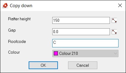
Rafter height - defines the offset, usually the rafter height.
Gap - defines an additional gap if you want to refer to the exact rafter height.
Roofcode - Defines the code of the roof plane. The code of a roof plane is a tag which determines the behavior of the generation and stretching of hsbWalls.
Colour - The color of the roof plane. The color of a roof plane can also be derived from its corresponding color index where the alphabetical index of the character equals the color index,
i.e. A = 1 (red) , B=2 (yellow), C=3 (green) etc. To enable the automatic coloring you must enable it in the hsbSettings/Colors/Set roof planes by color
Merge Roof Planes

One can merge roofs to receive complex roof shapes. you define multiple roofs and finally merge simple roofs to a complex one.
- Select hsbPlanes\Merge Roof Planes.
- Select the roof planes to be merged together.
Subtract From Plane

One can subtract a closed polyline from a roof plane. When you subtract a closed polyline from the hsbPlane the polyline will be projected to the plane and a polyline shape cut out of the plane.
To subtract a polyline
- Select hsbPlanes\Subtract from Plane
- Select the roof plane(s) to be added to and then
- Then select the 2d polyline to add to the hsbPlane.
Add To Plane

Add to plane will allow you to add a closed 2d polyline to an existing hsbPlane. When you add a closed polyline to the hsbPlane the polyline will be projected to the plane and the plane
continues at the same angle if it is sloped.
To add a polyline to a plane.
- Select hsbPlanes\Add To Plane
- Select the roof plane(s) to be added to.
- Then select the 2d polyline to add to the hsbPlane.
Create Floor under Roof

You can create a floor plane under roof planes.
Modify hsbPlanes
Assign Profile
You can assign a predefined roof profile /section to an existing roof icon.
- Select roof icon, then select the roof section or polyline roof section representation.
Adjust Icon Slope
You can change the slope of a roof plane and adjust it to existing roof planes.
Define Ridge Line
The function of this command is to define the location of the ridge of two roof planes.
The slope of one roof plane will be changed while the other remains unchanged.
Using the command Define Ridge Line you can move the ridge line parallel to the existing one. The ridge line will stay on the same height.
Rooficon 1point
You can define a ridge point.
This point will be the ridge point for all selected roof planes.
You can select one main roof icon and multiple child roof icons, i.e. the slope of the main roof icon won't change and the slope of the child roof icons will be adjusted to the ridge point and the main roof plane.
This function is used, for example, to calculate bay roofs.
Rooficon 3 points
You can calculate the icon for a roof plane when the required values such us angle, or height at beginning of the eaves are not available or trustworthy.
It enables the user to generate a
3D roof plane, and obtain exact values for unknown heights and angles, by using information from very simple 2D top and front views.
Project Polyline in Roof
You can project a closed polyline on a roof plane.
Solid to Roof
You can convert the top planes of solids (AutoCAD 3D-solids) into roof planes.
BLOCK_WARNING_START
It doesn't work with vertical or horizontal planes.
BLOCK__END
Convert From/to ADT Roof
The function of this command is to convert an adt roof or roofslab into hsbcad roof planes or vice versus.
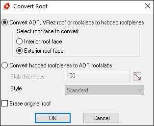
- Convert an ADT roof to a hsbcad roof - you can select if the interior or exterior face of the ADT roof will be converted into a hsbcad roof plane.
- Convert a hsbcad roof plane into an ADT roof - you can specify the thickness of the converted slab.
Dormer Roof
Dormer Roof - Doghouse

Use the Dormer Roof command if you want to create a dormer.
- Select one of the 3 options
Doghouse - Dormer with a gable style front.
Shed - Dormer with a sloped front.
Trapezium – Gabled roof dormer or a sloped roof dormer.
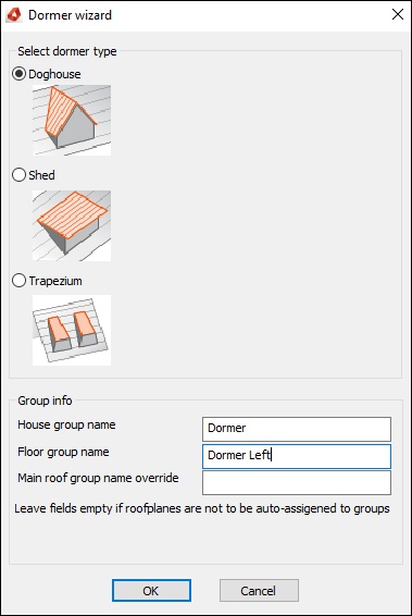
The function of this command is to create doghouse dormers.

Definition mode - one can determine the definition mode.
with a horizontal offset to the ridge
with a vertical offset to the ridge by specifying the wall height
Slope - defines the slope of the dormer
Stand - defines the stand of the rafter. The stand is the distance of the base of the birdsmouth to the top of the rafter, measured plum or perpendicular to the roofplane.
Main roof properties –
Dormer properties - specifies the properties of the dormer.
Hip doghouse dormer - enabling this option will create an hip doghouse dormer. The eave offset defines the offset from the main dormer eave to the hip eave.
How to draw a dormer roof
- Select hsbPlanes\Dormer Roof.
- Select with the left mouse button a roof plane.
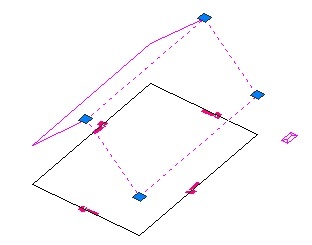
Confirm with the right mouse button.
Fill in dialog box Dormer generator and confirm with OK.
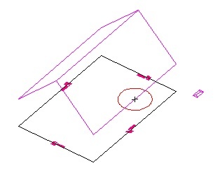
- Select with the left mouse button a point of the dormer ridgeline at eave of the main roof (this point is the first point of two points which defines the direction of the dormer)
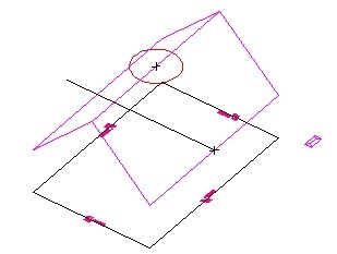
- Select with the left mouse button a point of the dormer ridgeline at ridge of the main roof. (this point is the second point of two points which defines the direction of the dormer)
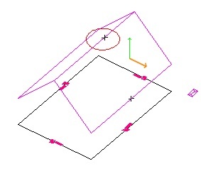
- Select with the left mouse button any point on the main roof plane. This point is for setting the height of the dormer (depending on the selection in dialog box Dormer generator: Vertical or Horizontal offset).
If you selected vertical offset only the coordinate of the point in orange direction will be considered.
If you selected horizontal offset only the coordinate of the point in green direction will be considered.
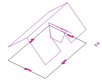
Result
Dormer Roof - Shed
The function of this command is to create shed dormers.
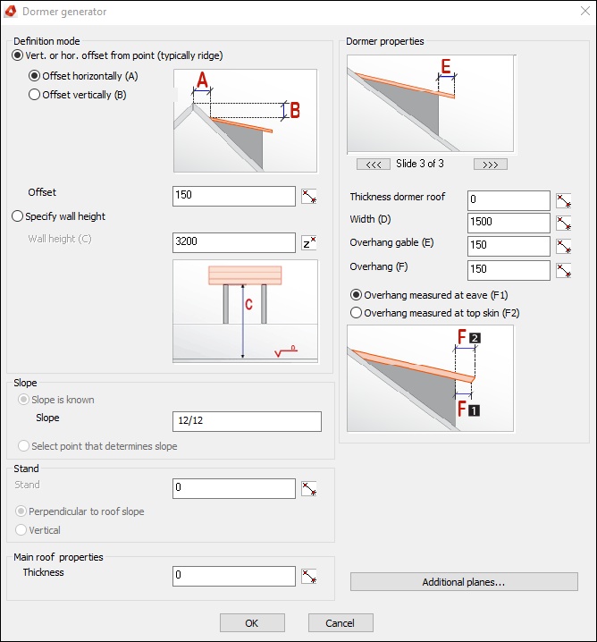
Definition mode - one can determine the definition mode.
with a horizontal offset to the ridge
with a vertical offset to the ridge by specifying the wall height
Slope - defines the slope of the dormer
Stand - defines the stand of the rafter. The stand is the distance of the base of the birdsmouth to the top of the rafter, measured plum or perpendicular to the roofplane.
Main roof properties –
Dormer properties - specifies the properties of the dormer.
Dormer Roof - Trapezium
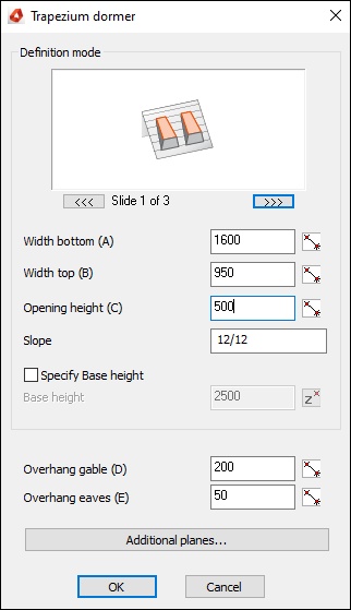
The function of this command is to create trapezium dormers.
Fill in the necessary information in the following dialog box.
Create a Dormer Wall

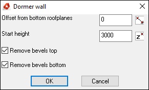
The function of this command is to create a dormer wall.
You can stretch a wall upward and downward to roof planes or rather cut at roof planes.
You can specify the offset from the bottom roof planes as well as the start height.
Optional bevels at bottom and top can be removed.
How to create dormer wall
BLOCK_CHECK_START
Roof planes and walls should be already designed.
BLOCK__END
- Select hsbPlanes\Create a Dormer Wall.
- Select with the left mouse button bottom roof plane. (you can select more than one)
- Select with the left mouse button top roof planes. (you can select more than one)
- Select the dormer wall.
Section Wizard

Add section
You can create sections / profile of roofs.
Using this roof sections / profiles you can design roof planes.
With the help of roof planes you can generate or rather create the roof construction (plates, rafters, girders, etc.).
You can also insert plates, windows or openings into the section / profile and assign it to the roof later on.
Add Plate beam from section
You can insert an additional plate into a roof section / profile.
Add section window
You can apply a window to a roof section / profile.
Add section fixed lath
You can insert a fixed lath into a roof section / profile.
If you insert two fixed lathes all lathes between will be evenly distributed.
Add plate beam
You can assign a plate beam from the roof section / profile to the roof plane.
The plate beam will be generated automatically.
Add roof window
You can assign a window out of the roof section / profile to a roof plane.
Add laths
You can assign laths of a roof section / profile to a roof plane and you can generate the laths.
Link section with roof plane
Change hsbPlane Code
After a plane is created you may want to change the planes code.
Change Code
- Select the hsbPlane to be changed and right click Properties, the Properties bar will appear and here you can change the hsbPlane Code (for wall envelope) to a different single letter (A-Z).

