How to insert tools in the hsbWall Details in hsbcad 2017 and earlier
BLOCK_CHECK_START
If you want to return to the original document How to make hsbWall Details in hsbcad 2017
BLOCK__END
How to insert a Set Limit (See video 8:16)
This command allows you to Set the length of beams in detail drawings (Wall Detail, Opening Details, H1, H2, H3, H4, T1, T2, E)

- Select the Set Limit function in the ribbon.
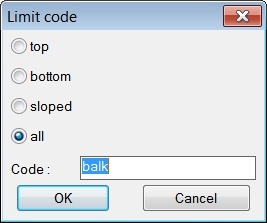
- This will open the Limit code dialog box.
- Fill in the necessary information. (Enter a code or enter Balk)
- Select a point in the drawing and then the direction.
- Select the Link Entities to Wall outline.
- Save Detail changes.
Limit code (Dialog box Explanation)

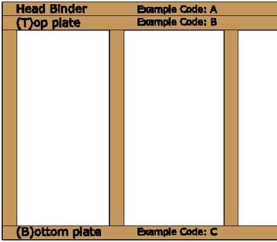
When creating a new Wall type you could call the beams something like this.
- A= Head binder
- B= Top Beam (Plate)
- C= Bottom Beam (Plate)
BLOCK_CHECK_START
To extend the Beams in the horizontal way you use the abbreviations (beam code) of the beams you have given.
To extend the Studs in the vertical way you enter BALK or Beam.
BLOCK__END
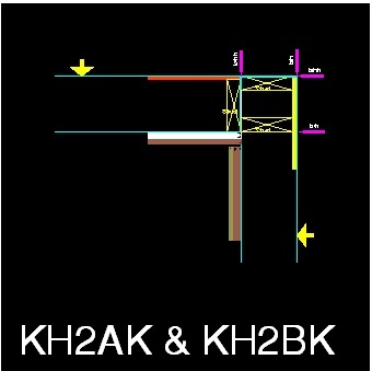
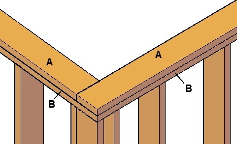
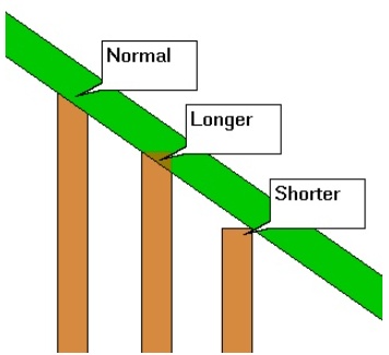
In this example we have made the head binder longer on one side and the Top plate shorter.
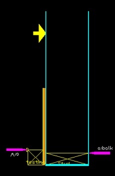
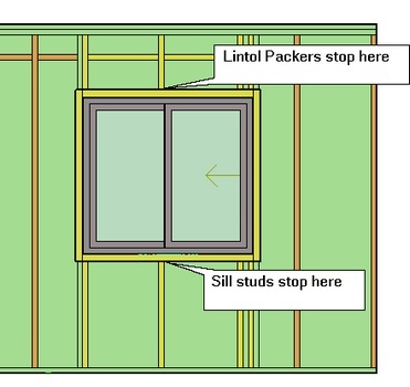
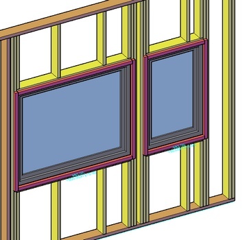
Limits for opening types
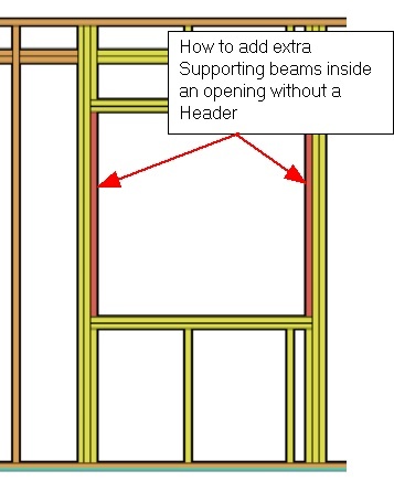
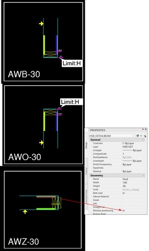
When using limits in opening Details you must give the surrounding beams a Window positioning code.
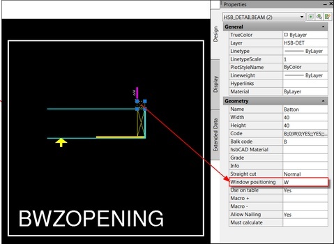
Name – Enter a name for the beam.
Width – Enter the width of the beam.
Height – Enter the height of the beam.
Code – Do not enter anything, this info is a combination of the Balk code/hsbcad Material …. ect.
Balk Code – When using limits, enter a Beam code.
hsbcad Material – Enter the beam material.
Grade – Enter the grade of the beam (strength of the beam).
Info – Enter extra information.
Straight cut – Select Normal/shorter/Longer. Will take the longer or shortest beam length.
Window positioning – When using limits in opening Details you must give the surrounding beams a Window positioning code.
Use on table – Select Yes or No. (Does this need to be exported to the Weinmann machine).
Macro+– This is obsolete (used by older hsbcad versions)
Macro-– This is obsolete (used by older hsbcad versions)
Allow Nailing – Select Yes or No. (Do you allow the nailing on this beam)
Must calculate– ………………
How to insert a Saw line
This command allows you to create a saw cuts on beams and sheets. You will see a saw line in the 3D‐drawing later on.

- Select the Saw function in the ribbon.
- This will open the Saw dialog box.
- Fill in the necessary information.
- Select a point in the drawing and then the direction.
- Select the Link Entities to Wall outline.
- Save Detail changes.
Saw (Dialog box Explanation)

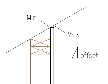
vershoot – 0/1, Vacuum 0/1, Offset, Side (1= max,0= none,1= min) Do you wish the saw cut to cut past the end point of the cut.
Overschoot – 0/1 no/yes
Vacuum – 0/1 if it needs to use the vacuum or not
Offset – allows you to enter an offset distance.
Side – is the side of the cut. It could look like the follow 0, 0, 30,1
Zone – This refers to the sheet zone which is being cut.
On – On/Off
BLOCK_CHECK_START
THIS IS FOR THE WEINNMAN MACHINE
BLOCK__END
How to insert a Mill (Milling element)
This command allows you to mill on beams and sheets. Later on you can see a milling line in the wall representation.

- Select the Milling Element function in the ribbon.
- This will open the Milling dialog box.
- Fill in the necessary information.
- Select a point in the drawing and then the direction.
- Select the Link Entities to Wall outline.
- Save Detail changes.
Milling (Dialog box Explanation)
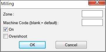
Zone – This is the sheeting zone you wish to attach milling lines to.
Machine Code (blank = default) – Depends on the machine. They may have a specific tool code to use.
On – This means you are going to use these setting rather than the machine defaults.
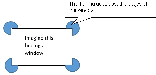
Overshoot – Would you require that the tooling goes past the end (overshoots) of the milling line. This is machine specific.
How to insert a Drill (See Video 18:12)
This command allows you to insert drills on beams and sheetings in your detail drawings (H1,H2,H3,H4).

- Select the Drill function in the ribbon.
- You will be prompted to enter a Diameter.
- Then the Starting height.
- Then the Spacing.
- Then the Machine (B/P(zone).
- Select the Start point and the end point.
- Select the Link Entities to Wall outline.
- Save Detail changes.
Drill (Dialog box Explanation)
Diameter – 20
Starting height – 150 (dimension starts from the bottom of the Element to the center of the drill)

Spacing – 450
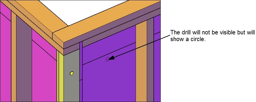
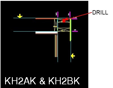
Machine (B/P(zone) – B (B= beam P=sheeting), if you use P set the zone behind it, for example P1. The drill will not be visible but will show a circle.
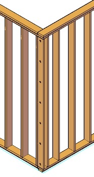
How to Mill a beam (Milling Beam) (See video 14:00)
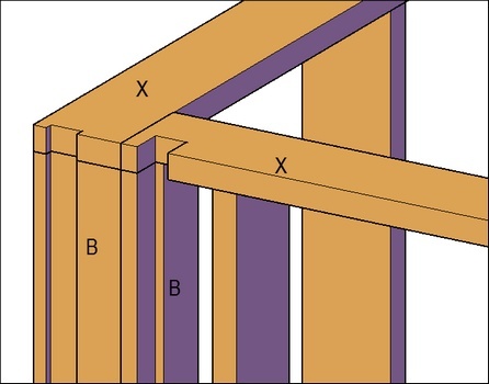
This command allows you to mill a beam in your detail drawings.

- Select the Milling Beam function in the ribbon.
- You will be prompted to enter the dx direction.
- Then the dy direction.
- Then the Code.
- Then the Connection Code.
- Select the point where the milling symbol has to be placed and then the direction.
- Select the Link Entities to Wall outline.
- Save Detail changes.
Milling Beam (Dialog box Explanation)
Dx – Enter the milling dimension in x direction.
Dy– Enter the milling dimension in Y direction.
Code– Enter a beam code to which the milling should be applied to. (In this case it’s X)
Connection Code– Enter the connecting beam code, if you want a cut in those beams too. (In this case it’s B)
How to place a Cut (See video 16:15)
This command allows you to add a cut to a beam in your detail drawings.

- Select the Cut function in the ribbon.
- This will open the Cut dialog box
- Fill in the necessary information.
- Select a point in the drawing and then the direction
- Select the Link Entities to Wall outline.
- Save Detail changes
Cut (Dialog box Explanation)
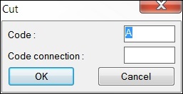
Code – Enter the balk code of the beam so it can place a cut on this beam, use a ‘’*’’ if you want to cut through all the beams.
Code Connection – Enter the connecting beam code, if you want a cut in those beams too.
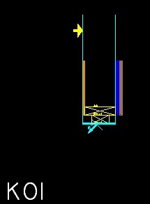
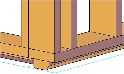
Example of how the Cut is shown in the drawing.
How to place horizontal Blockings
This command allows you to add horz. Blockings in the detail drawing (T1,T2).
You must attach the Horz.Blockings to the wall running from left to right.
- Select the Horiz.Blocking function in the ribbon.
- You will be prompted to enter the Thickness of the beam.
- Then the Starting Height(dimension starts from the bottom of the
- Element to the center of the first beam)
- Then the Spacing
- Select the starting pointin the drawing.
- Select the Link Entities to Wall outline
- Save Detail changes
Horizontal Blocking (Dialog box Explanation)
Thickness – 38
Starting height – 150 (dimension starts from the bottom of the Element to the center of the first beam)

Spacing – 450
Start point – 38 mm right of the top beam in this drawing.
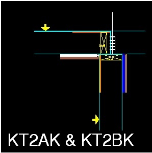
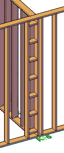
BLOCK_WARNING_START
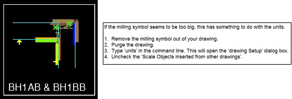
NOTE: If the Horizontal Blocking symbol seems to be too big, this has something to do with the units.
BLOCK__END
1. Remove the Horizontal Blocking symbol out of your drawing.
2. Purge the drawing.
3. Type units in the command line. This will open the drawing Setup dialog box.
4. Uncheck the Scale Objects inserted from other drawings.
5. Insert the Horizontal Blocking symbol again.

BLOCK_CHECK_START
If you want to return to the original document How to make hsbWall Details in hsbcad 2017
BLOCK__END
Link Entities to Wall outline
This command allows you to link the new beams, sheets, milling or saw lines and so on to the detail it belongs to. If you don’t link the new entities (changes) to the detail or wall Outline your new entities (changes) won’t be saved in the detail.

- Select the Link Entities to Wall Outline function in the ribbon.
- Select with the left mouse button all entities / objects of the detail.
- Confirm with the right mouse button.
- Select with the left mouse button the Wall Outline of the detail.
- Confirm with the right mouse button.
- Save Detail changes.
Reset Wall Details
This command allows you to reset details to the origin status.
For example if you want to re‐use an existing Wall type Code you need to Reset Wall Detail

- Select the Reset Wall Detail function in the ribbon.
- Select the square which needs to be reset.
- Save Detail changes.
Update New Details in DWG
This command allows you to update details of newly defined walls. Already defined details of old walls won't be changed.

- Select the Upload New Details function in the ribbon.
- The update will automatically start.
- Save Detail changes.
Update Walls with new description
This command works automatically when you want to update the wall with a new description or have changed anything in your Wall detail and you go to your H1‐H2‐H3‐H4‐T1‐T2‐E, the changes are done automatically.

Save Detail Changes
This command allows you to save all changes in the detail drawing and the database.

- Select the Save detail Changes function in the ribbon.
- All the changes you have made have now been saved
BLOCK_CHECK_START
If you want to return to the original document How to make hsbWall Details in hsbcad 2017
BLOCK__END

