Revit® | Detail Editor
This document will show you the way you can work with our detail editor.
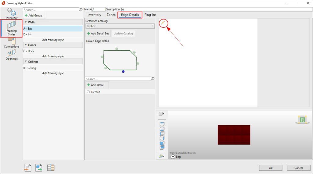
The editor can be opened from the Framing Styles Editor.

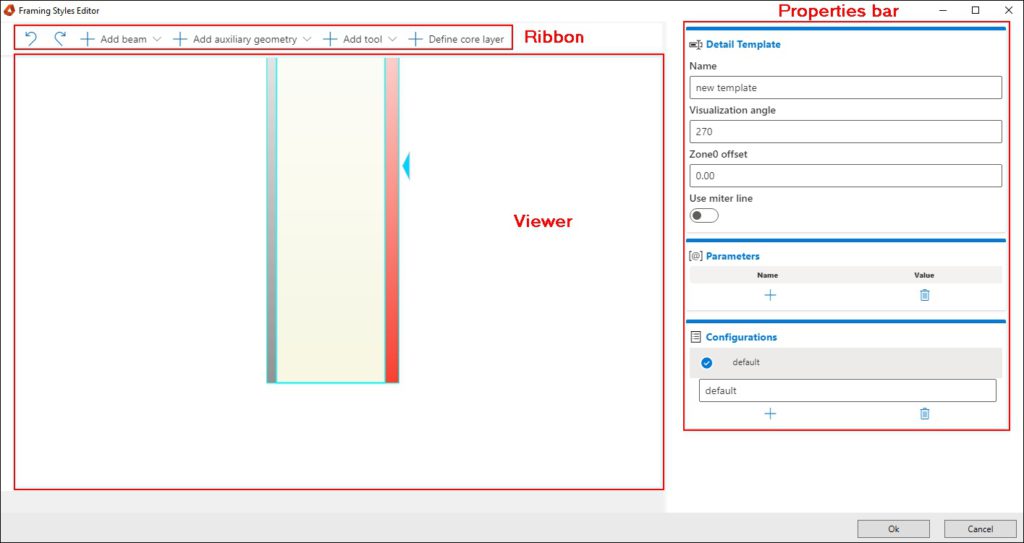
You can find 3 different areas in the detail editor:
- In the Ribbon you can add or manipulate some objects from inside the viewer
- In the Viewer you have a 2D representation of your detail
- In the Properties bar you have multiple properties you can manipulate to create your specific detail.
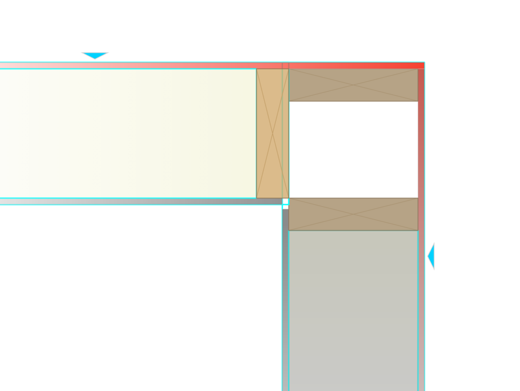
The detail editor is different when you configure a single detail or a corner connection, with two or more connections.
Ribbon
Add beam
In the beams section of the ribbon you have the option to select three manipulations:

- Add a beam to the highlighted detail.
When you click this option a beam will be automatically inserted. If you are manipulating a connection detail, the beam will be added to the highlighted part of the connection. - Add free beam.
Adds a loose beam to the detail. This beam is not anchored (Read: viewer). - Copy selected beam.
A beam will be copied next to the selected beam. The beam will not be anchored, even if the selected beam is anchored.
Add Auxiliary Geometry
The auxilliary Geometry ribbon gives you tools to add to the viewer in order to anchor or cut your details in the way you would like to.

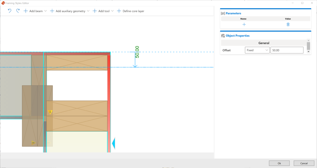
Offset line
This tool allows you to create a line that can be used in your detail. This line can be placed anywhere in your model and has a parameter that can be manipulated during the configuration of the detail.
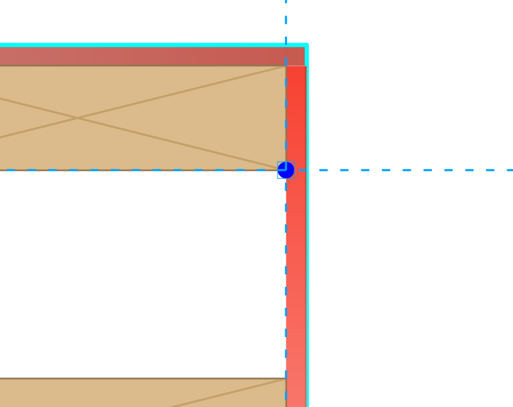
Intersection Point
When selecting the intersection point you can create an intersecting point. You have to select the first line and then the second line and on the intersection point, it will create a point that you can use to manipulate your detail.
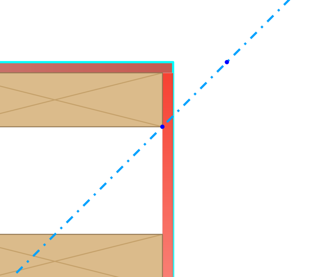
Line from two points
This allows you to create a line by selecting two points.
Add tool

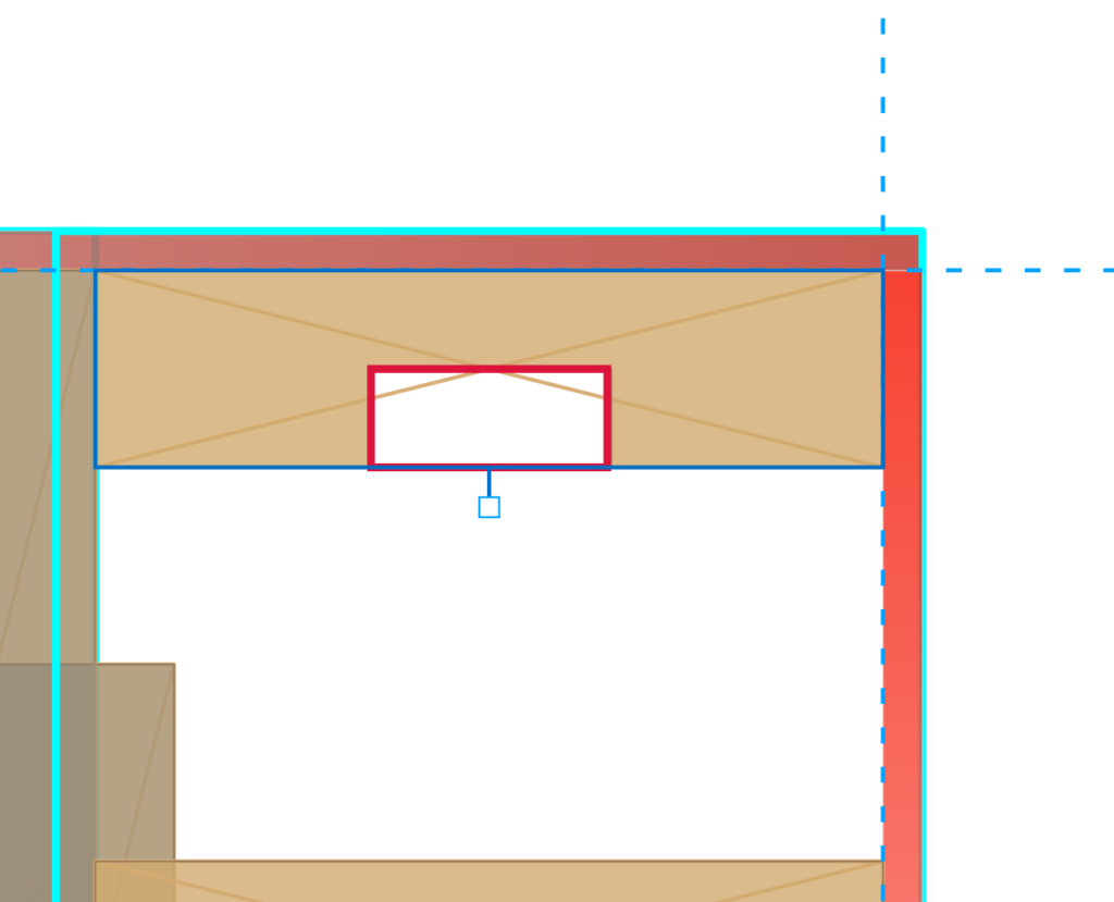
Add milling
After you have selected the milling tool, you will notice a red box appearing in the viewer. This box will create your milling tool in the detail. You can manipulate the tool by setting the properties.
Add cut
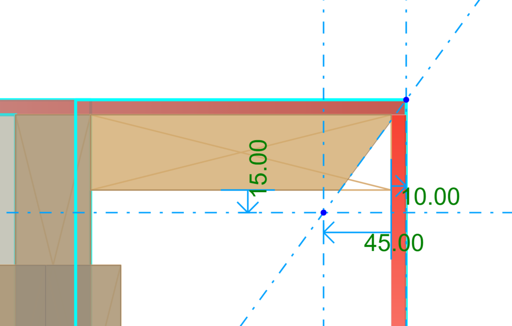
The cut tool enables you to create a cut operation on beams. You can insert the cut tool by selecting it in the ribbon.
- It will ask you for a line to associate your cut with.
- After selecting the line it will ask you what side you would like to cut away.
- As a third step, you need to select the detail you want to enable to cut on.
Add sheet cut
You have the same functionality with the sheet cut as you have with the normal cut. The sheet cut, however, is designed to cut sheets with a particular line. The insertion process is the same as above. You can insert the sheet cut tool by selecting it in the ribbon.
- It will ask you for a line to associate your cut with.
- After selecting the line it will ask you what side you would like to cut away.
- As a third step, you need to select the detail you want to enable to cut on.
BLOCK_INFO_START
The sheet cut can only be inserted in T-inside and T-outside connection types
BLOCK__END
Define core layer

Todo
Viewer

Viewer functionality
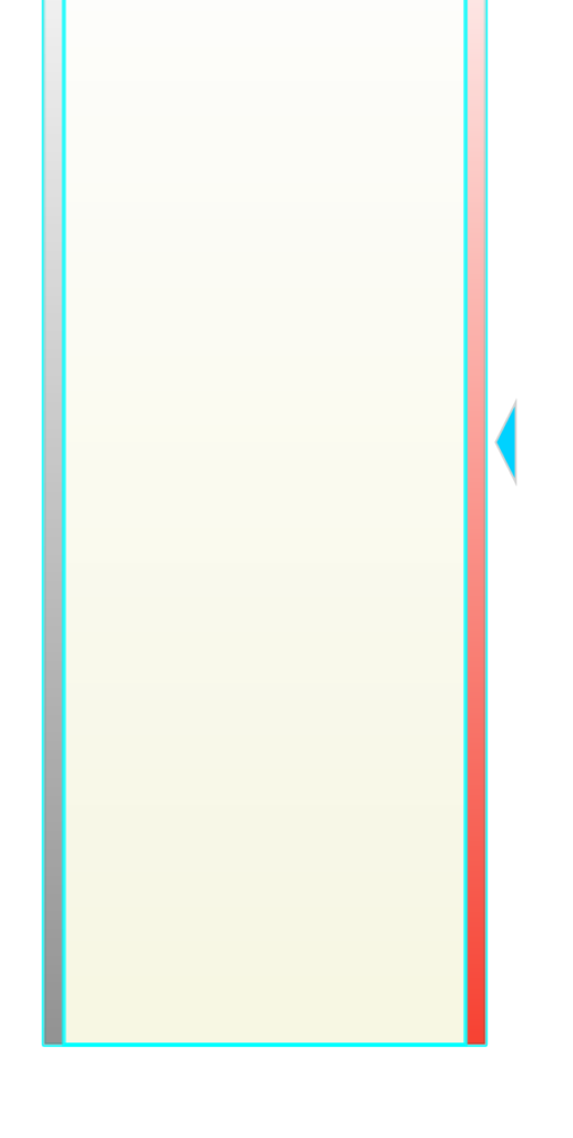
In the viewer, there are multiple objects available to view, but in most cases, you will start off with the core layer and sheets on the left, right, bottom, or top. After you have added some beams you can see the functionality of the viewer when selecting a beam.
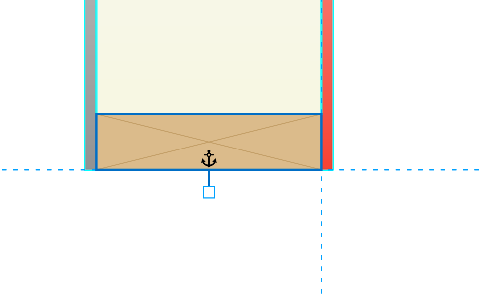
The viewer has some icons as you can see, such as the anchor point and the rotation/move point.

Anchor point
You can select and deselect an anchor point. Selecting an anchor point means that the item you have selected is being anchored (attached) to a certain line or point. This means that if you change the line or the point, the item will automatically position itself, anchored to the line or point. You can easily deselect an anchor by selecting it again.

Rotation/Move point
If you have a beam that is not anchored to anything, you can rotate that beam. You can select the rotation point (see above) and by holding down the mouse button you can rotate the item to the preferred position.
If the move point is on a sheet, then you can stretch or shorten your sheet with the move point.
Properties

Detail Template
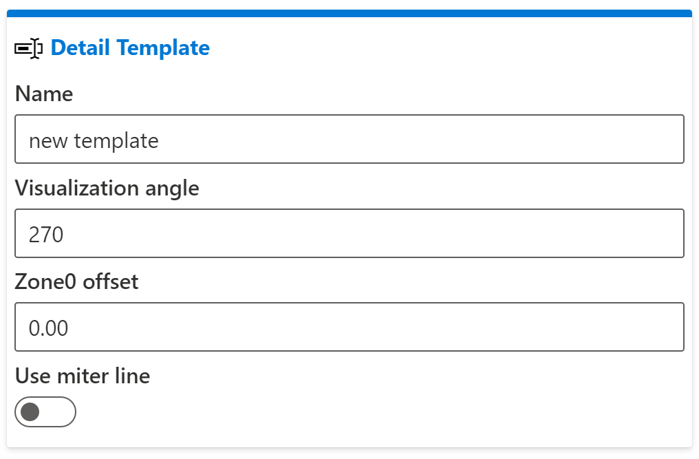
In the Detail Template properties you can manipulate your properties from your detail.
Name: The name that will be shown in your Framing Style Edit (FSE)
Visualization angle: The angle on how you would like to see your detail
Zone 0 offset: The offset of your structural layer
Use miter line: If you enable this function there will be a miter line automatically created for you,
Parameters

You can create and use any parameter you would like.
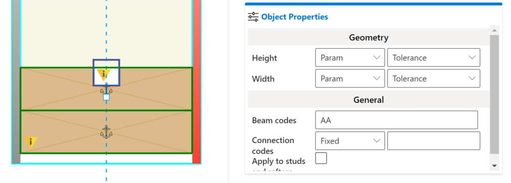
This can be used in creating your model. In the example below, you can see that the parameter Tolerance is being used to set the height and the width of the milling tool.
Configurations
You can create multiple configurations of a single detail. This allows you to work with the same detail but with slight adjustments based on parameters. These configurations will also be selectable in your Revit drawing while detailing your model.


