Essential Guide to Revit® | hsbStickFrame for Autodesk Revit® (Video)
This document will show you the different actions on the hsbStickFrame Ribbon in Autodesk Revit. This will give you an idea of how you can detail your Revit model with hsbcad's hsbdesign software.

Tutorial
https://www.youtube.com/watch?v=nKNSPOaS3LY
Configuration
Framing Styles Editor

With the hsbStickFrame for Revit you can use any system type from Revit to create your framed result. The main thing you need to do is create your framing styles. These styles will be matched to your system types in Revit and will be the core of your detailing process.
Selecting the first button in the hsbStickFrame ribbon will open up the Framing Styles Editor. For more information on setting up your framing styles, we redirect you to the Framing Styles Editor page.
BLOCK_INFO_START
A framing style is needed to create more details in the drawing. Without this framing style, it will be impossible to frame your Item Container.
BLOCK__END
Match Framing Style

Once you have created your framing style, you need to match this style to a certain system type in Revit.
BLOCK_INFO_START
A system type is a wall, floor, or roof type in Revit.
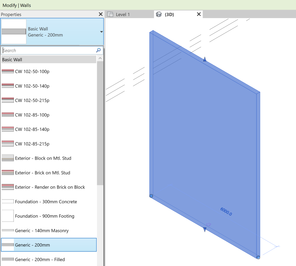
Example of walls in the Revit library
BLOCK__END
Match your framing style to your system type
Select Match Framing Style in the ribbon and the hsbcad Settings dialog box will open up, select the Framing tab.

The window is divided in three screens.
- System family types
- hsbStickFrame style
- Visual representation of your system type and your framing style
1. System family types
This list contains the System Types that you can find in your active Revit model. Here you can filter, based on a search string or through the Type dropdown.

Below that, the Show Types filters the list for types in use in the drawing or not.
When you select the filter, Show types in use, the list below will only show you a list of items that have an instance in your active Revit model.
2. hsbStickFrame style
This section of the window allows you to select the framing style that needs to be mapped to the selected system type. After selection, you can modify the alignment, change the arrow side and add an offset to the aligned framing style.

- Element Style: In this dropdown you find all your created framing styles within the framing style editor.
- Arrow Side: Here you can flip the arrow side of the system type to interior or exterior in order to match your framing style.
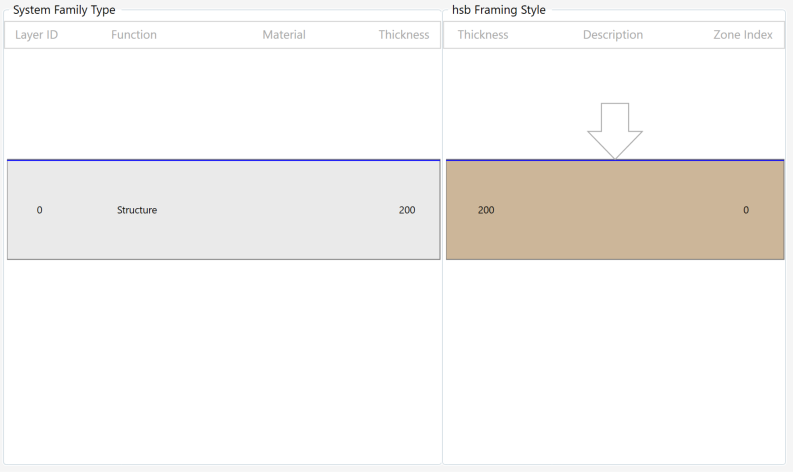
- Alignment: This gives you the option to align your framing style with your system type. The blue line within the 2D representation gives you the line where the framing style will be aligned to.
- Offset: Here you add a value to align your framing style even further. The offset will be added from the blue line in the opposite direction of the arrow.
BLOCK_INFO_START
You can open the framing styles editor from this window. In that framing styles editor you can create a new framing style, or modify an existing one.
BLOCK__END
3. Visual representation of your match
In the third part of the window, you can find your 2D representation of the system type and the framing style. The blue line represents your alignment line. The arrow is your reference to the wall. The location of the wall will be different from the way you draw a wall. If you draw it from left to right, the wall will be on the outside of the wall, if you draw the wall from right to left it will be on the inside of the wall.
Containers
Item Containers

This tool creates an item container for your system type. To perform an action, such as automatic framing, you need to have item containers attached to your system type (wall, floor, roof).
To create an item container, you can click on the item container command and select your system type (wall, floor, or roof). A multiple selection is also possible. This will automatically attach an item container object.

Item Containers for Linked Elements

This function combines the functionality above with the functionality of using a linked model. All you need to do is select your system type from your linked model and you can start framing your linked model.
Add to item Container

You can add more items to an item container with this command. If you want to add beams, metal parts or other items to your shop drawing or export results, you need to use this function.
Remove from item Container

When you have added something to the item container by mistake, this is the tool to remove it again.
Item Container Renumber
Details
Update connections

When you have configured your connections in the framing styles editor, you can press this button and it will create and/or update new connections between your item containers.
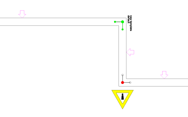
These connection details can be selected to make modifications or to see if they have been configured correctly or not. The connections shown in green are configured and you see your connection name next to it. The connections in red give you an alert symbol and for this connection, there is nothing that can be framed.
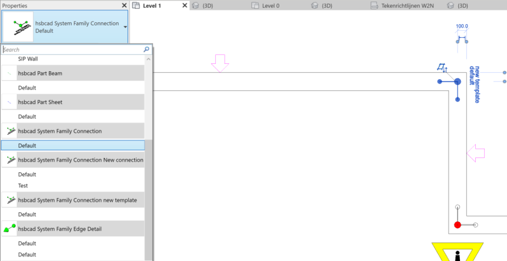
You can easily change your connection type with the native Revit properties toolbox. After you click on the connection, you can go the dropdown and select your preferred connection.
Update details

When you have configured your framing styles, you can create edge details in your drawing to modify these while detailing. Every edge of your item container will receive an edge detail.
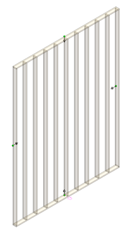
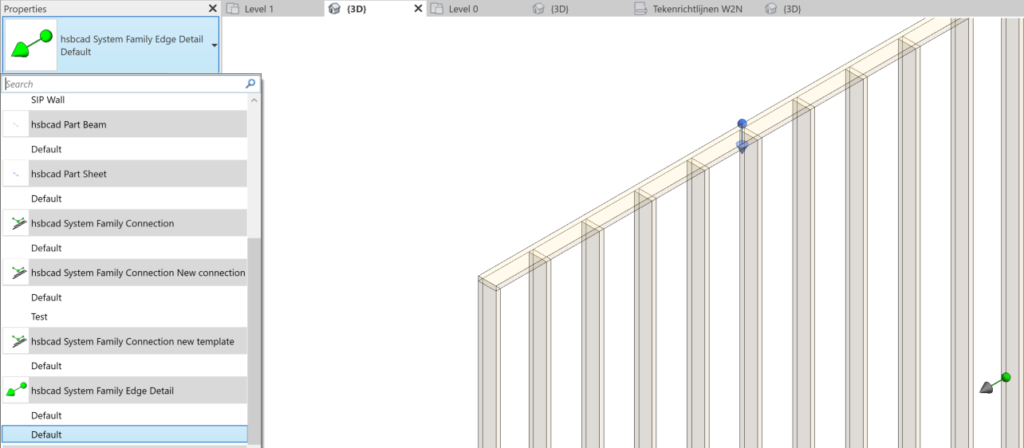
You can easily change your edge detail with the native Revit properties toolbox. After you click on the edge detail, you can go the dropdown and select your preferred connection.
Framing
Generate

This command let's you frame the configured item containers.
Insert
Select the command.
Select your item container which you want to frame. (multiple selection is possible)
Press Enter or finish.
The product will automatically frame your item containers.
Remove

This command let's you undo the framing for an item container.
Insert
Select the command.
Select your item container which you want to unframe. (multiple selection is possible)
Press Enter or finish.
Tools
Tools for framing
You find more information in the tools section for framing: tools for framing
Shop drawings
Shopdrawings

Create for container

With this functionality you can create your shopdrawings for item containers. The first step you will need to do is load the template you want for your item containers. As a second step you need to select your item containers. For these item containers the software will automatically create shop drawings.
Load your shop draw template (only once)
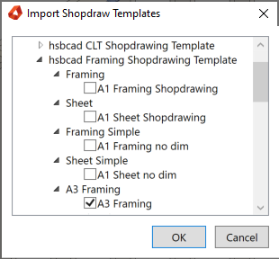
- Select your template to use for the creation of the shop drawings
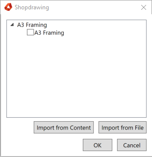
Select your item containers and your shopdrawings will be created in the Sheets tab of your Project Browser
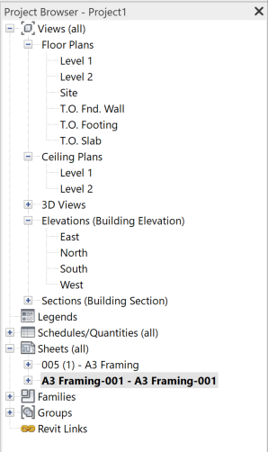
The result is a shop drawing

Activate Shopdrawing Template

Sets current sheet to Shop drawing Templates.
Add Tags

You can add tags to your shop drawing with this function. This allows you to add information to beams, sheets, and other elements within a view. You need to select a view before trying to add a tag to the view.
Add View Tags
Add View Section Anchor
Add 3D View Anchor
Add Schedule Anchor
Dimensions
Element Diagonal
Element Framing
Opening Horizontal
Utilities

Console

You can navigate fast through your detailed model with the console. Opening this tool adds a tab next to your project browser and gives you an overview of every item container on each level.
Recalc

Recalculate hsbcad elements.
Insert
Trigger hsbcad Coded Family Extensions to execute.
The elements connected will be re-created.
This can solve possible issues with hsbcad families.
Create PosNums

Add position Numbers to structural members.
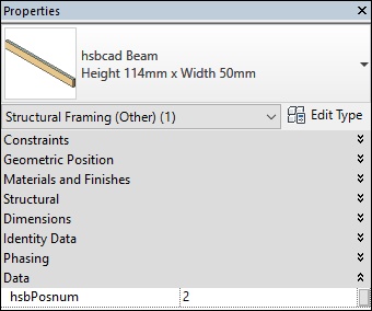
The hsbPosnum parameter value is set after analysis of the selected solid(s).
Each equal solid will get the same value, this number can be used for identifying objects for machining and ordering purposes.
Insert
Select the command.
Select the Structural Members, you can select with a window or select an individual Structural Member (a plus mark appears when Structural Member hasn‘t been selected yet).
Deselect the Structural Members by reclicking or window select (a minus mark will appear on Structural Members that already have been selected).
In order to finish or cancel the selection go to the options bar.
You can also confirm selection by pressing <enter>.
After finishing the Posnum Settings dialog will pop up.
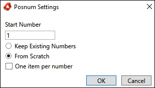
You can select the Start Number, this will be the number that will be assigned to the first beam. The rest of the beams will get an increasing number.
The keep existing numbers option will not overwrite the current value of the PosNum parameter.
The From Scratch option will delete the existing value of the PosNum parameter and assign new numbers from scratch.
After finishing the hsbPosnum parameters value is assigned to the “hsbRevit Beam”.
BLOCK_ALERT_START
The hsbPosnum parameter can be overwritten manually, but this is not recommended.
BLOCK__END
Support Tools

This adds Support Tools.
Support Tools: This adds Support Tools. (LINK to external page)
Export
Export manager

Sends an hsbcad model to the hsb export manager. The hsb export manager is a separate application outside hsbcad that can export an hsbcad model to a variety of file formats. From machine files to formats like .ifc and .pdf
More information about the exporter: hsbexporter
hsbShare

Send your model to hsbshare. An app to facilitate communication channels between project owners and stakeholders, for sharing of extended meta data orientated around a 3D model. This centralized tool is shared among design offices, site teams and building owners
Settings
Settings

Select to customize the hsbcad settings.This shows a dialog where you can configure the hsbcad settings.
Help
hsbacademy

Provide access to online help and other resources.
hsbAcademy user Guide LINK to this External page.
Account Info
More information on Purchase Options, Account info, app update, About.
Purchase Options

This option will direct you to the website for more info.Account Info
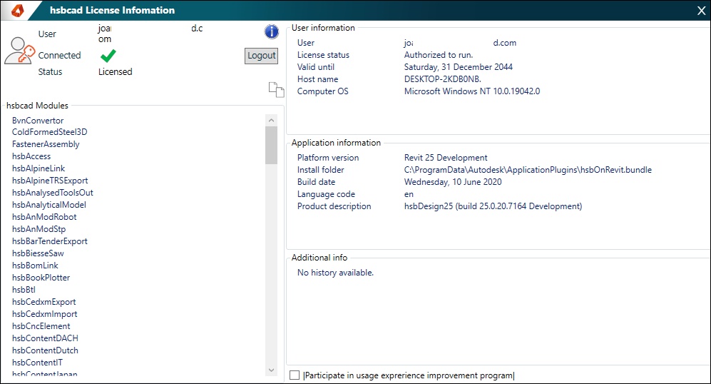
Account Info
Gives you License information.
Update

Update: Updates the hsbDesign to the latest release available
Repair: The Repair option will force an update to the latest available release.
The update option will check for the most recent available update and will not update if none are available.
Update/Repair LINK to this External page.About
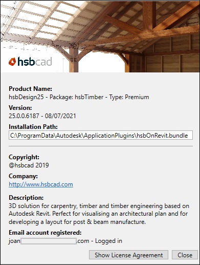
About

Displays the information about your current version of the installed hsbDesign plugin.
More video’s of hsbStickFrame
Revit® | hsbStickFrame in a nutshell for Revit®
Revit® | How to install hsbStickframe for Revit®
Revit® | hsbStickFrame for Autodesk Revit®
Revit® | Creating Framing Styles for Revit®
Revit® | Match Framing Styles for Revit®
Revit® | Create Edge Details for Revit®
Revit® | Create Connection Details for Revit®
Revit® | Butt Connection for Revit®
Revit® | Framing a Wall for Revit®
Revit® | Framing with Persist Technology for Revit®
Revit® | Framing an Opening for Revit®
Revit® | Structural Blocking for Revit®
Revit® | Tools for hsbStickFrame®
Revit® | Setting up Shop Drawings for Revit®
Revit® | Creating a Pocket for Revit®
Revit® | Creating a Point Load for Revit®
Revit® | Creating a Vent for Revit®
Revit® | Working with Validations for Revit®
Revit® | Cripple Studs for Revit®
Revit® | Notch plates for Revit®
More video’s of hsbStickFrame on hsbDesign25
Revit® | Framing Style Editor Enhancements on hsbDesign25 for Revit®
Revit® | Import and Export in hsbDesign25 for Revit®
Revit® | Linked Files on hsbDesign25 for Revit®
Revit® | Profiles on hsbDesign25 for Revit®
More video’s of Revit® on hsbDesign26
Revit® | Item Container Lock for Revit®
Revit® | Family Version Control for Revit®
Revit® | Span direction on floors and roofs for Revit®
Revit® | New Shop Drawing User Interface

