How to make hsbWall details - Wall Detail Builder hsbDesign22 /23 /24 /25 /26
This article will explain how to make Wall Details in a new Stickframe using the Wall Detail Builder.
Starting the Wall Detail Builder
BLOCK_ALERT_START
Use the Wall Detail Builder only in a new Stickframe.
Start with an empty folder called Stickframe in your hsbCompany(C:\hsbCompany\Stickframe
Do not combine with the previous Wall Detail system (pre 2017).
If you don't have an empty Stickframe just make a new folder called Stickframe, it should look like this C:\hsbCompany\Stickframe
BLOCK__END
BLOCK_WARNING_START
Warning: The Stickframe folder is strictly for storing your Wall Details, built in the Wall Detail Builder.
It should NOT be accessed through the file explorer.
Files should NOT be copied, moved, or renamed in this folder.
The only way to access your Stickframe details is to edit them in the Wall Detail Builder. In other words DO NOT TOUCH your Stickframe folder.
BLOCK__END
BLOCK_CHECK_START
You can have Multiple Stickframes, obviously they will have different names but they need to be prefixed with Stickframe.
BLOCK__END
To start the Wall Detail Builder, run the command hsbWall\hsbWall Details\Wall Detail Builder or select Wall Detail builder in the Ribbon.

The following dialog box will open, containing:
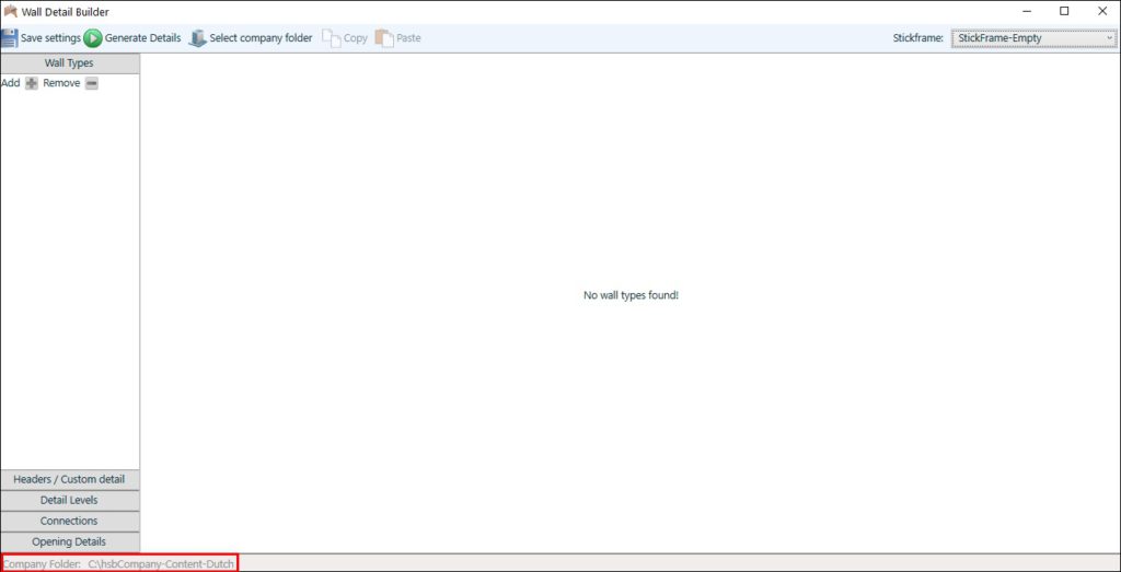
Wall Types
The wall types section has two main buttons.
When adding a new wall, the Wall Types dialog can be divided into five different sections.
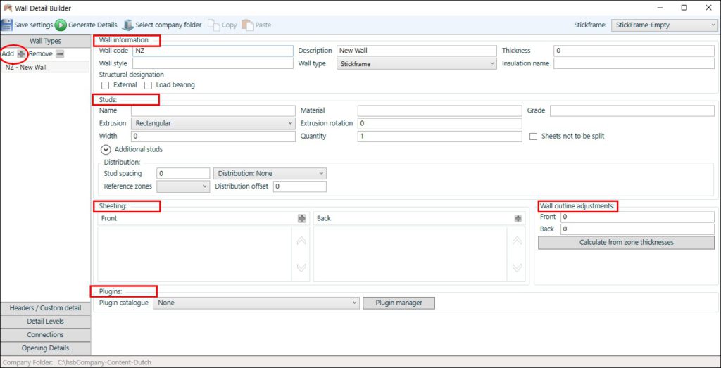
Wall information
BLOCK_WARNING_START
Wall code may not end with 'W'
BLOCK__END
BLOCK_CHECK_START
Structural designation: these field can be used later on in the Filtering for example in the hsbMake (Production street)
The load-bearing walls go to the left lane, the Outer walls to the right lane, the rest are produced on the middle lane.
These data fields are written to hmlx files and are not visible in the model.
When you make an export of your drawing, this is exported to an hmlx (data file) and with the exporter you can also filter on these fields. (eg. a report without outer walls etc..)
BLOCK__END
If your Wall type is Firewall there are some additional options:
Firewall Width: Enter the firewall Width (drawing 100)
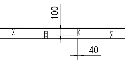
Thickness: Enter a name for the firewall studs

Grade: Enter the firewall Thickness (drawing 40)
Name: Enter the grade of the firewall studs
Material: Enter a name for the material of the firewall studs (e.g. Fir)If Wall type = Firewall
Options:


Studs
Enter the width of the studCheck the box if you don't want to get split sheeting at this locationEnter the zone for the reference of the distribution offsetAngle of the profile rotates around the X axisVisual DistributionReference zoneEnter a description of the studThere are different types of distributions to select fromGradeUse the Additional studs to enter the information of a second, third,.. studExtrusionEnter a name for the materialQuantitySheets not to be splitZoneWidth of beamAdditional studs Input the delta value. This means the distance from the wall end to the center of the first stud, where the distribution should start fromEnter the grade of the woodEnter the number of the studs. For example: if you input the number two there will be two studs on the distribution position instead of oneInput a number for the zone. The distribution of the sheeting will be dependent on this zone. Distribution zone works in conjunction with Distribution types. The sheet zone(s) that you want the studs to distribute by (from 1 to 10)Stud spacingNameDistribution offsetExtrusion rotateMaterialEnter the extrusion profile name of the beam (only used when you have made extrusion profiles)Enter the spacing distance for the studs
Name: Enter a description of the stud
Material: Enter a name for the material
Grade: Enter the grade of the wood
Extrusion: Enter the extrusion profile name of the beam (only used when you have made extrusion profiles)
Extrusion rotate: Angle of the profile rotates around the X axis
Width of beam: Enter the width of the stud
Quantity: Enter the number of the studs. For example: if you input the number two there will be two studs on the distribution position instead of one
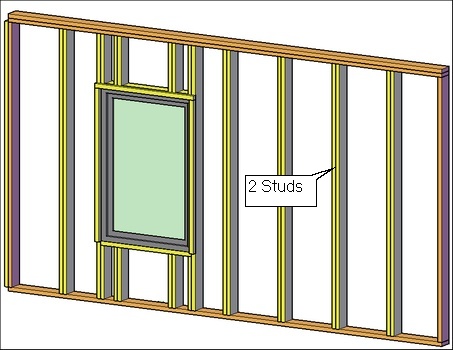
Sheets not to be split: Check the box if you don’t want to get split sheeting at this location
Additional studs: Use the Additional studs to enter the information of a second, third,.. stud

Stud spacing; Enter the spacing distance for the studs
Reference zone: Enter the zone for the reference of the distribution offset
Distribution offset: Input the delta value. This means the distance from the wall end to the center of the first stud, where the distribution should start from
Visual Distribution: There are different types of distributions to select from
Zone: Input a number for the zone. The distribution of the sheeting will be dependent on this zone. Distribution zone works in conjunction with Distribution types. The sheet zone(s) that you want the studs to distribute by (from 1 to 10)

For example you could be using Visual distribution type 4 with Reference zone set to 1. What this will do is start you distribution from the left most point of your sheeting to allow sheeting maximization. By default distribution 4 will start left on a wall if no sheeting is on zone 1.
If you do have sheeting on zone 1 and it doesn’t start at the beginning of the wall, the stud distribution will start at the left most point of the sheeting.
Sheeting distribution
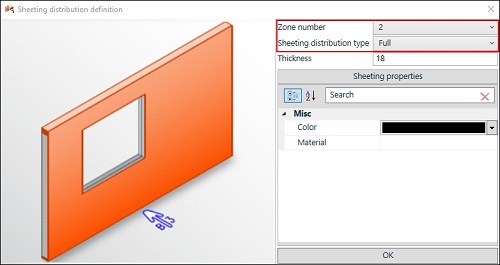
Use the '+'icon to add a sheet to a specific zone, '-' to delete a sheet, the pen to change the information. Use the up and down button to change the order of the sheets.
BLOCK_INFO_START
Front are zones 1 to zone 5
Back are zones 6 to zone 10
BLOCK__END

When creating or changing a sheet, the dialog box for the Sheeting distribution definition will open. In this dialog box you can change the zone number and the Sheeting distribution type.
Wall outline adjustments
Use calculate from zone thicknesses to adjust the wall outline.

Front and Back with the value: Wall outline contours Zone 0

Using Calculate from zone thicknesses: Wall outline contours all the zones

Plugins
- Select the Plugin manager to open the dialog box Element Plugins.
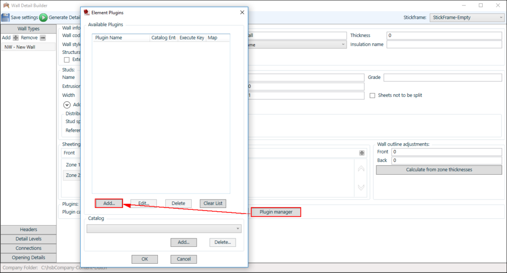
- Use Add to Define the plugin you want to insert. By selecting the three dots, a list with plugins (tsl's) will appear.
BLOCK_INFO_START
These tsl's refer to you hsbCompany\TSL folder
BLOCK__END
- Select the desired plugin, select a Catalog Entries if available.
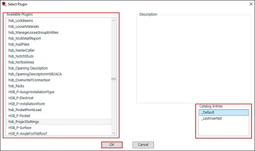
When imported as an available plugin, you need to add the plugin to your catalog.
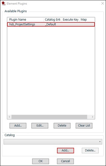
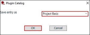
Select now the correct entry in the catalog.

- Save the settings.
Headers / Custom detail
When working with details General, Geometry and Position are the main groups which contain different properties.
In the tab Headers, change the Default Detail to Custom Detail to work in a specific detail.
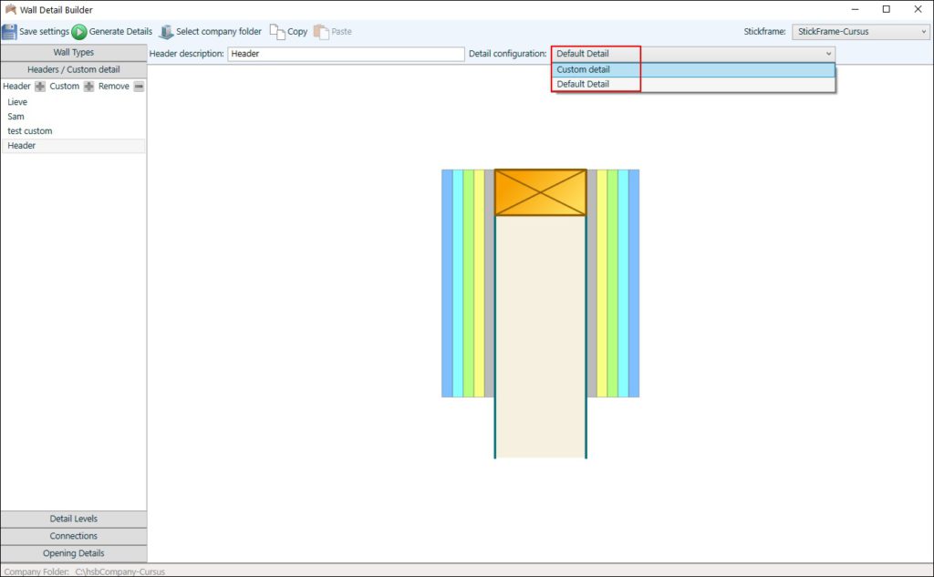
When selecting the zone 0, the info Geometry will open on the right side of the screen.
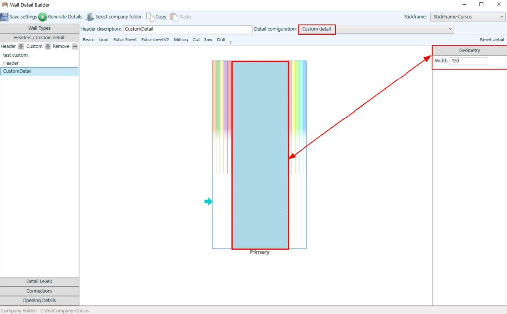
Default the geometry width is 150. The width is only for visualization and does not apply to the width of a wall or the detail level groups.
Different properties to use:
When selecting a sheet or a beam, additional properties will appear:
Use the Geometry to change the geometry properties of the beam:
How to use the anchors
BLOCK_INFO_START
Use the cancel sign to cancel an assignment
BLOCK__END
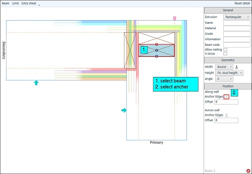
- Click on the beam you want to move.
- Select the Achor Edges, 3 dots will appear in that beam.
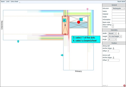
- Select the dot you want to use as a reference.
- Select the sheet or beam you want to refer to. 3 dots for a beam, 1 dot for sheet will appear.
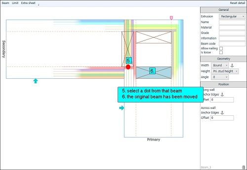
- Select a dot from the referring sheet or beam.
How to use the functions in the geometry
Bound – if you want to have the beam the same geometry as e.g. a sheet or another beam.
How – select the beam, select bound, click on the ancher, select e.g. a sheet
Fixed – use a fixed height or width
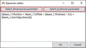
Use previous stud height Expression – create an expression in the editor, it allows you to Select dimensional and positional parameter from other beams.
How to use limits
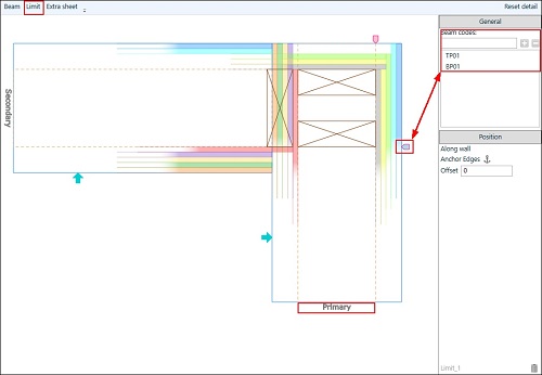
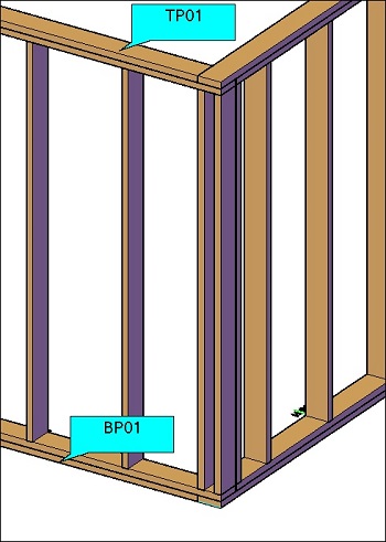
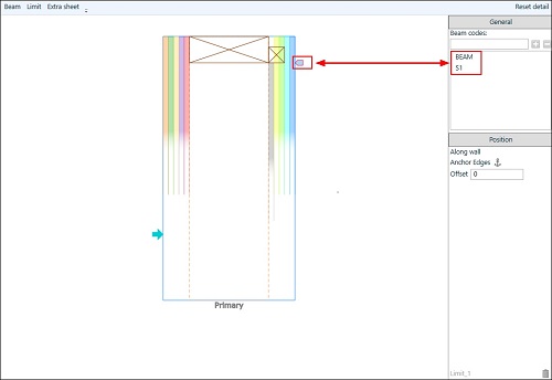
In order to use the limits, beam codes should be filled in for the beams.
You can add a Limit in the Primary or Secondary wall, just by selecting the zone 0 and clicking on Limit.
Select the added limit icon, and add the beamcodes for that limit by using the '+' sign (multiple beamcodes are possible).
Headers
Use Add to create a new header.
Change the name of the header in the Header Description.
Detail levels
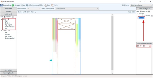
On the left side you will find the Levels you have created. Each level contains a Top, Bottom, Top angled, Bottom angled Detail.
BLOCK_INFO_START
Only Level 0 has a End Detail
BLOCK__END
On the right side you will find the Detail Level groups you should create and a list with the unassigned wall types. For each Level you can create a Detail Level Group.
Assign Wall Types
Assign the wall to which group they belong to.
Connections
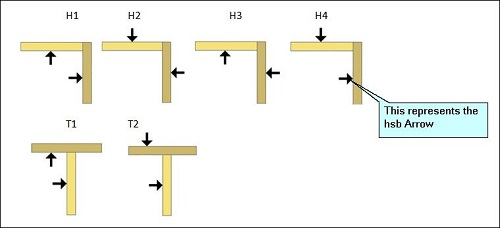
On the left side you will find the different Connections. H1 - H2 - H3 - H4 - T1 - T2 - E
Each Connection has the possibility to link two Connection Group Types. So each combination for each types of walls is possible.
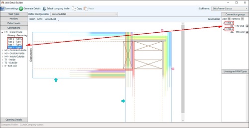
H1 – Inside corner
H2 – Outside corner
H3 – Outside - Inside corner
H4 – Inside - Outside corner
T1 – Inside T detail
T2 – Outside T detail
Opening Details
On the left side you will find the Opening Details you have created. Each detail contains a Top, Bottom and Side detail. On the right side you will find the Opening detail groups, create different types an assign the wall types.
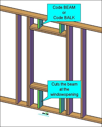
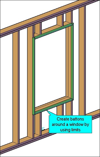
To use the functionality Limits in the Opening Details, you can use the Beamcode 'BEAM' or 'BALK', this will cut the vertical beams going true the window opening.
How to create sheeting around opening
This command allows you to create specific sheeting around an opening. To define Sheeting around opening run the command hsbWall\hsbWallDetails\sheeting around opening or select Opening Sheets in the ribbon.

This will open the Windows – Sheeting dialog box.
Fill in a code and a suitable description at the top.
Fill in the values you want in the front and back of each opening.
Blue = Top of the opening
Green = side of the opening
Red = Bottom of the opening

Select the Save button.
To close this dialog box just select the X in the top right hand corner.
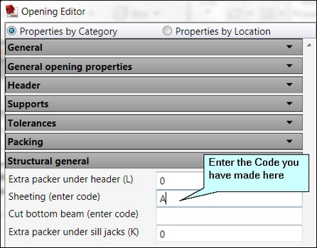
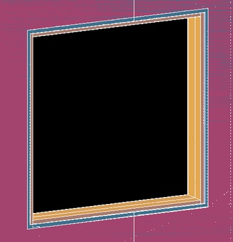
Example of where Sheeting around opening will be used. When you position an opening in your drawing with the command hsbWALL\Position opening you enter the code name of the sheeting detail in the Opening Editor Dialog box in the Structural general tab under sheeting.
How to use the detail code table
This command allows you to select detail codes contained with your detail library.
When you make a detail and you want to use this later on, to overwrite a certain beam or stud.

Select Detail Code Table in the ribbon.
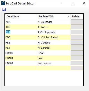
This will open the hsbcad Detail Editor dialog box. Fill in the detail code you find in the left hand bottom corner of each detail drawing.
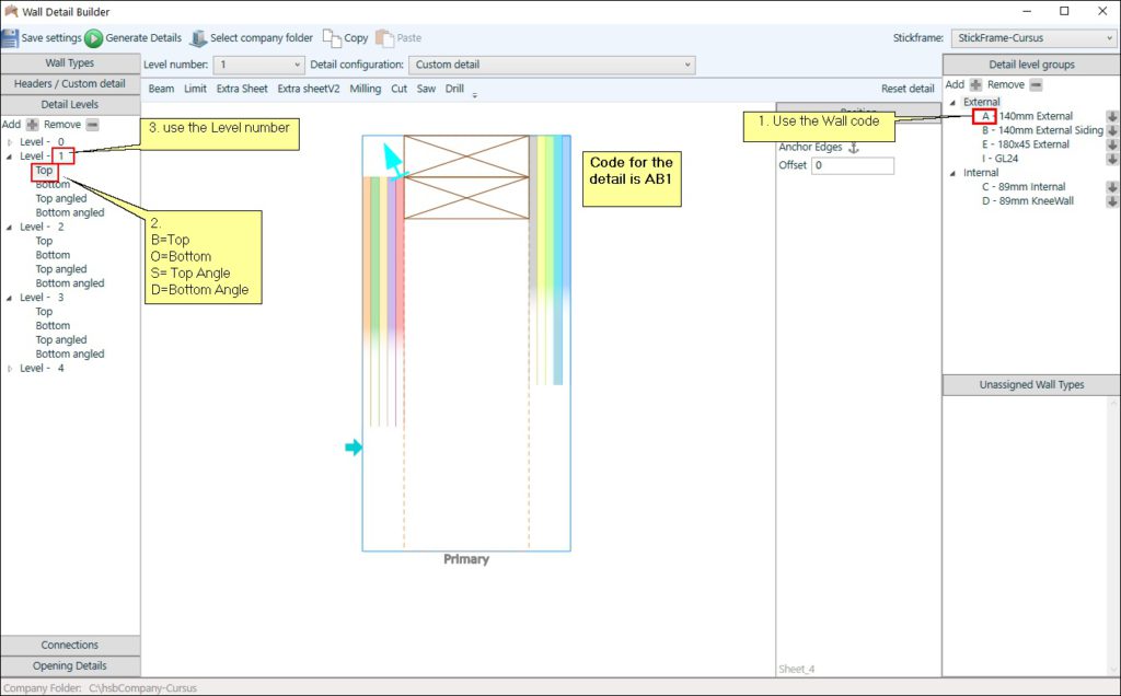
How to know your Code for a Detailoverwrite ?
Start with the wall code + Enter B for when you used a Top detail OR Enter a O when you used a Bottom detail + Enter the Level number you used. e.g.:
Fill in an appropriate name that will give you a hint what the function is of the detail.
Select the Save button in the top left corner of this dialog box.
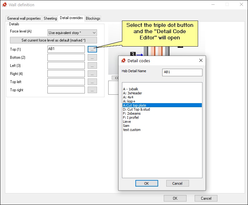
When you have made your details in your detail drawings and you use the command hsbWALL\Place Wall then you can use the Detail overrides tab to select a certain detail.
Select the triple dots and select the detail you want to use.
